-
Get It
$19.99
$19.99Civil 3D Essentials Book and Practice Files
Civil 3D Alignment by Layout (Alignment creation tools): A step by step tutorial guide
Introduction to Civil 3D Alignment by Layout (Alignment creation tools)
Firstly, how to create a Civil 3D Alignment by Layout (Alignment creation tools)? Well, let's find out in this online training course. Certainly, this step by step tutorial is a part of the Civil 3D essentials book and how-to manuals.
Working with Civil 3D Alignment by Layout (Alignment creation tools)?
The second way to create alignment is to use the Civil 3D Alignment by Layout - creation tools. These tools allow you to create an alignment using specific design conditions. It would otherwise be very difficult to achieve without these tools. The creation tools can also be used to modify an alignment once it's already created. Let's see a few situations where the Alignment by layout - Creation Tools are very handy.
- First, to launch the layout tools, from the ribbon, select the Civil 3D Alignment by Layout (Alignment creation tools).

- Next, enter Violets Circle for the name of the alignment.
- The type will be Centerline since this will represent the centerline of a street.
- For description, enter a text describing the purpose of the alignment.
- Then, do not specify any site, as we don’t need any interaction between the alignment and other design items.
- Afterward, for style, use Proposed to differentiate between proposed and existing alignment styles.
- The layer is set by default from the template settings, and there's no need to change it.
- Use the Major Minor H+V Geometry points to show major and minor stations, and horizontal and vertical geometry points.
- Finally, no need to change anything on the Design Criteria tab of the alignment by layout window.

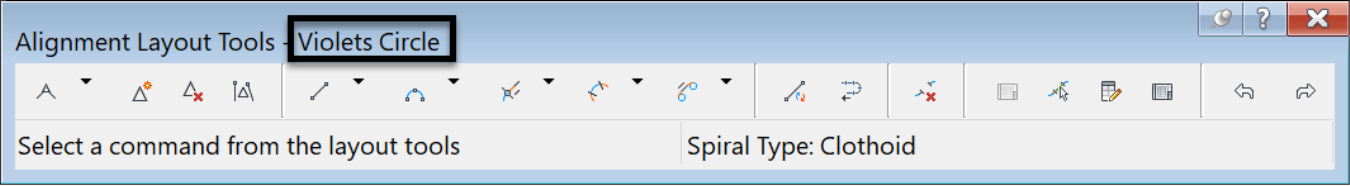
- The Civil 3D Alignment by Layout (Alignment creation tools) toolbar now opens. This toolbar will also indicate the name of the alignment you are currently working on. A close attention needs to be paid to this as sometimes, in the heat of the action, you may select the wrong alignment to edit.
-
The Civil 3D Alignment by Layout (Alignment creation tools) has several tools to perform site-specific design by layout. For example, you can:
- design tangents, curves, and spirals, with specifics tangency requirements.
- add or remove PIs (Point of Intersections),
- convert AutoCAD lines or arcs to alignment entities,
- reverse or edit created layout entities,
- delete or select sub-entities, and
- display a tabular view of design elements.
Now, let's explore a few of the tools of the alignment by layout creation tools.
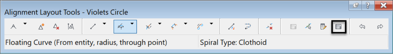
- First, we will be creating alignment by layout around a cul-de-sac with a 15m or 50ft radius requirement. So, let's set that parameter. On the creation tools toolbar, click on Curve and spiral settings.
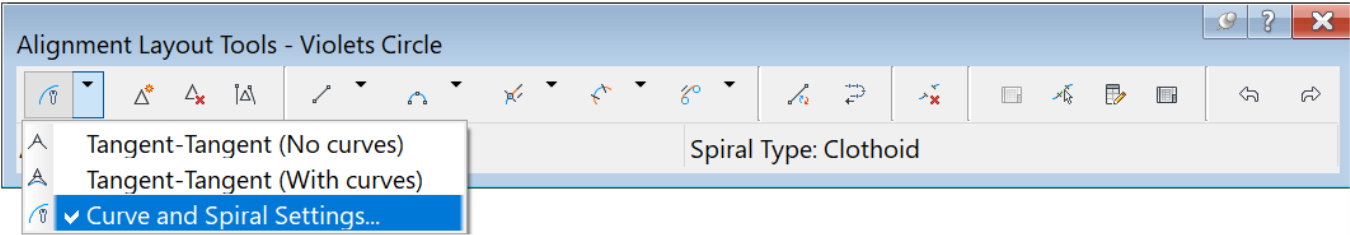
- In the next window, accept Clothoid as the default type of spiral. We are not creating any spiral in this case, so this is irrelevant. Check the Curve checkbox and put 15m or 50ft for the default curve value and click OK.

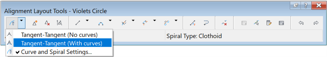
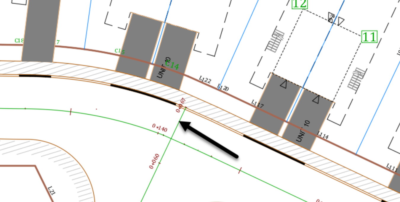
- Now, start designing the alignment by running the Tangent-Tangent (With curves) command from the creation tools. It will automatically create a curve with a radius value. Exactly like we specified in the Curve and Spiral Settings, whenever we create two subsequent tangents. As recommended earlier, whenever possible, always design your alignment from west to east and south to north. In this case, the alignment should start at the intersection of Lavender Court and Violets Circle. That point is pre-determined for us with the blue line centerline representing Violet Circle’s centerline. You can also create this line using multiple AutoCAD drafting options. One is to create two lines perpendicular to the curb line at each end of the street. Then, draw a line from the midpoint to the midpoint of these two lines. Or, you can use the AutoCAD constraints options to draw the centerline. But, this is not an AutoCAD course. Therefore, we will focus on Civil 3D alignment creation by layout tools and functionalities.
- Now that you are set up, you can use the Convert AutoCAD line and Arcs command to convert AutoCAD entities from the layout tools. This will create tangents and curves for the alignment.
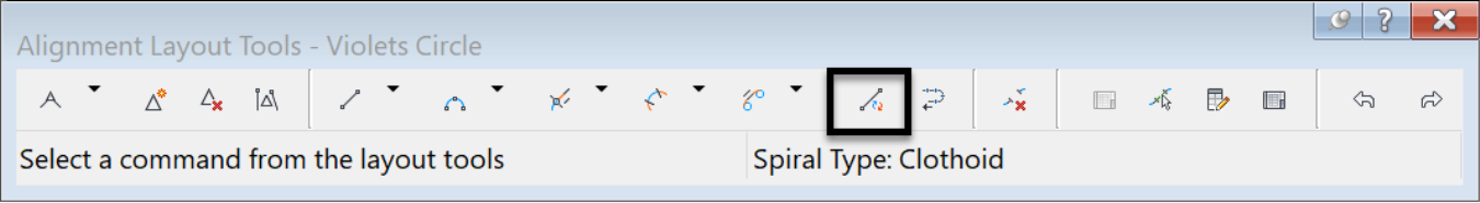
- Alternatively, you can use any of the line creation tools, if you know your start and endpoints.
- Or, the Tangent-Tangent (No Curves) command.

- The advantage of the Tangent-Tangent, (with or without curves), is that you can keep designing without exiting the active command of the layout creation tools.
- Let's use the Tangent-Tangent (With curves) command. Click at the intersection of the two streets, with your End object snap mode activated.
- Then, click on Point A, at the east end of the polyline on Violets Circle.
- Now, we are going to learn how to use fixed and floating line and curve entities of the creation tools.
- Floating entities are constraint-based alignment geometries. They will maintain tangency between adjacent objects.
- On the other end, fixed entities are fixed in their position, and must be edited directly. They are not affected by the geometry of adjacent entities and do not maintain tangency.
- The third type of entity is the free entity, line or curve of the layout tools. It is defined by not only one, but two entities, on which the free entity is dependent on them to define its geometry. An instance of this is a fillet between two curves.
- Let's start with a line entity between points A and B. If you have closed the Alignment Layout tools by mistake; you can always reopen it. To reopen it, selecting an alignment, then right-click and select Edit Alignment Geometry. Then you can, once again, edit the alignment or add additional data.
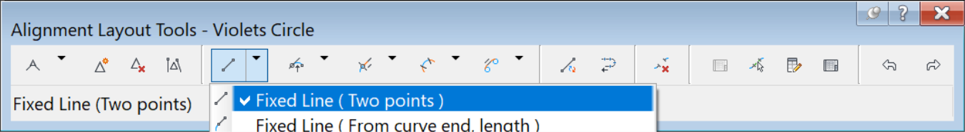
- After clicking a button on the Alignment Layout Tools, follow the prompts at the command line.
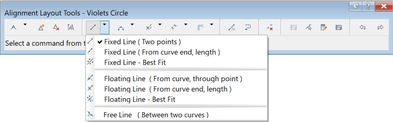
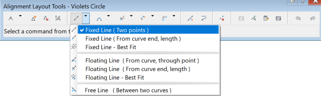
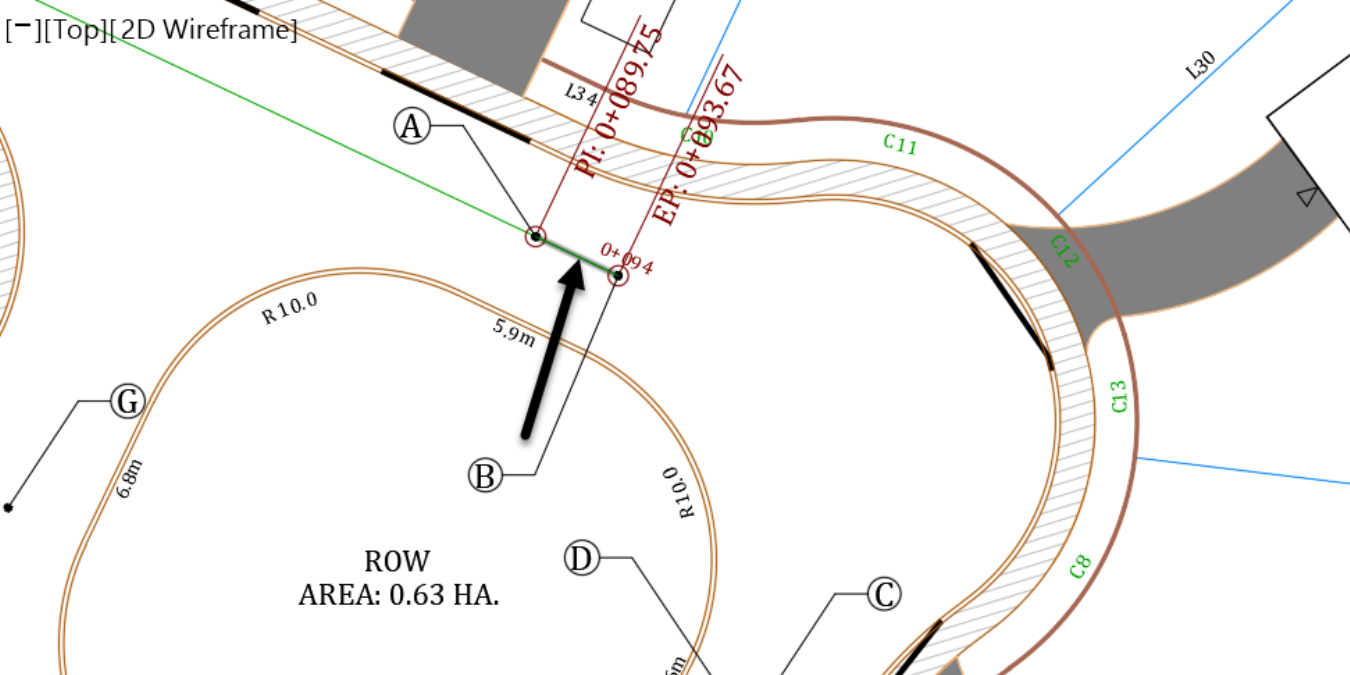
- What we want to do next is use the Fixed Line (Two points) command to add a tangent. Clicking on Point A then Point B. At each click, make sure the Center object snap mode is used.
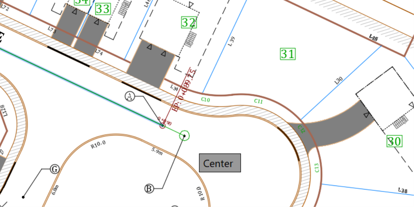
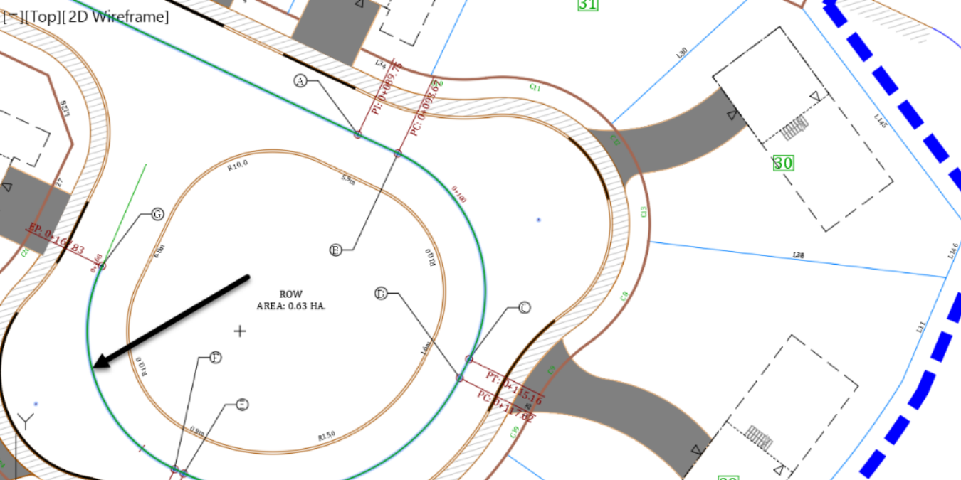
- Now what we want to do is create the centerline alignment of Violets Circle, in the cul-de-sac area. An island with inside curb line has already been created for us during the conceptual phase of the project. We need to create the centerline with a minimum travel way width of 3.5m or 12.5ft, on both ends of the centerline. A few reference points, from A to G, have been created for us to use.
- First, we need to connect Point A to Point B. For that to happen, from the Civil 3D Alignment by Layout (Alignment creation tools), you can use any of the alignment line creation commands. They can be Fixed Line (two points), Floating line or tangent-tangent.

- Next, we will go from PointB to C. Between these two points, the outside radius of the face of the curb is 10m or 35ft. Therefore, we need to create a centerline radius of 13.5m or 45ft. The new curve entity between B and C will also need to maintain a tangency, going from A and B.
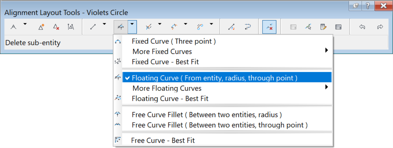
- The command that allows us to do that by using Floating Curve (From Entity end, radius, through point). Once you run the command from the layout tools, you are prompted to select the entity to attach the new curve to. Click on the line between A and B.
![]()
- Enter 13.5m or 45ft, when prompted to specify a radius, at the command line.
![]()
- For the curve solution angle, press Enter to accept a value less than 180-degrees.
![]()
- Then, when prompted to specify the Endpoint of the entity, click on Point C.
![]()
- We have now created a curve between B and C. Also, it is perfectly tangent to the previous line entity. Creating tangent and floating entities is one of the main benefits of the Alignment layout tools. It’s crucial to use these tools when highly accurate alignments are required. Especially when designing rail tracks, highways or airfields.
- Next, we need a line entity from Point C to Point D. Simply run a Fixed Line (Two points) command and click on the start and endpoints. Make sure the Object Snap setting is active, to connect the two points.
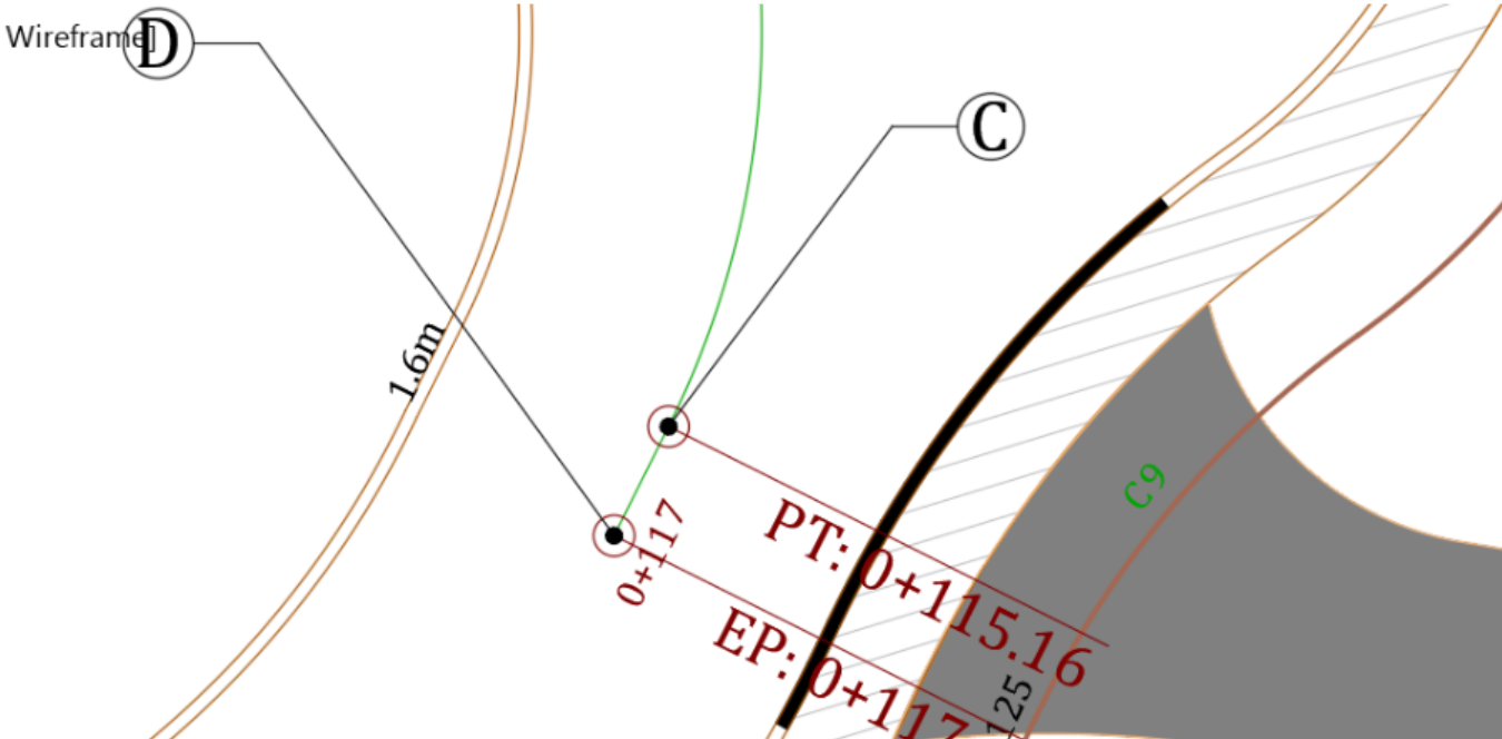
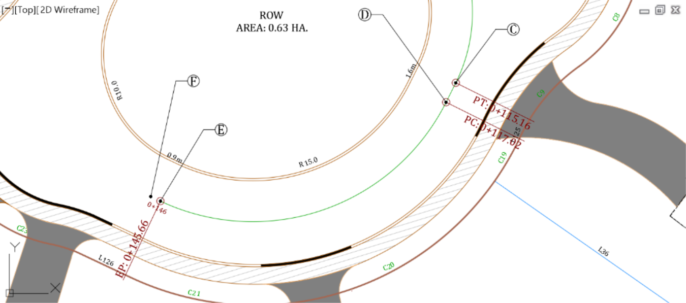
- Now that Point C and Point D are connected, we need to tie Point D to Point E, with an 18.5m or 60ft radius curve. Run the Floating curve (From entity, radius, through point) command from the layout creation tools.

- Select the line between Point C and Point D, when prompted for the entity to attach to.
![]()
- When asked to specify a radius, type 18.5m or 60ft
- For the solution angle, press Enter to accept an angle that is less than 180-degrees
![]()
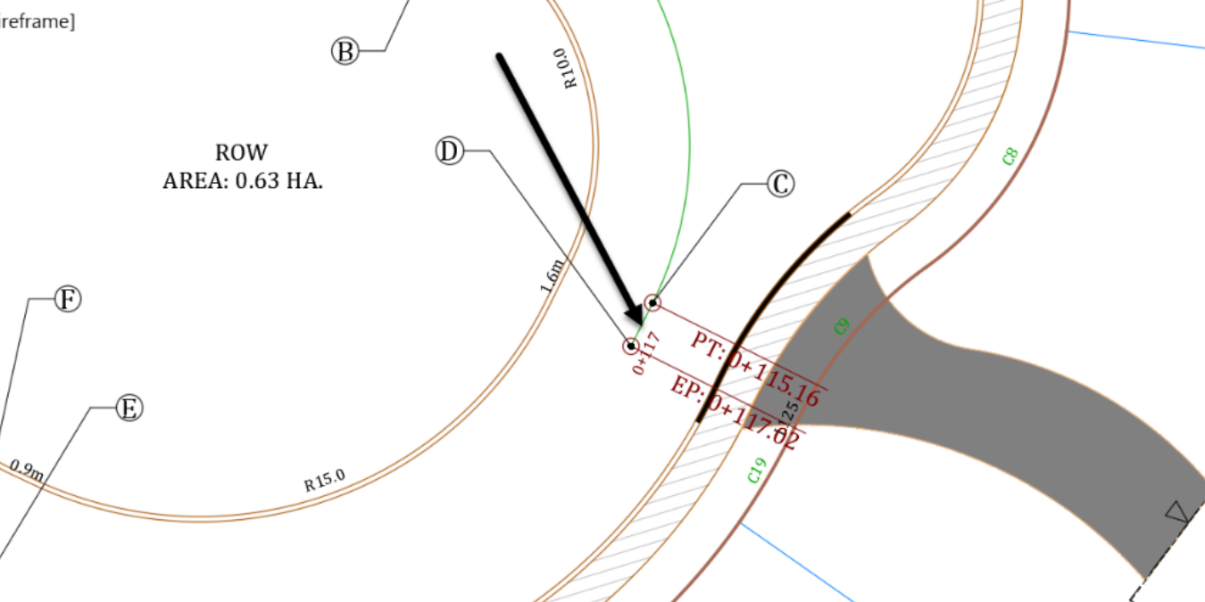
- Then, when asked to Specify Endpoint, click on Point E.
![]()
- We now have a curve created between points D and E. Moreover; it is perfectly tangent to the previous line entity.
- Next, create a tangent from E to F.
- Then, a floating curve from F to G, with a 13.5m or 40ft radius.
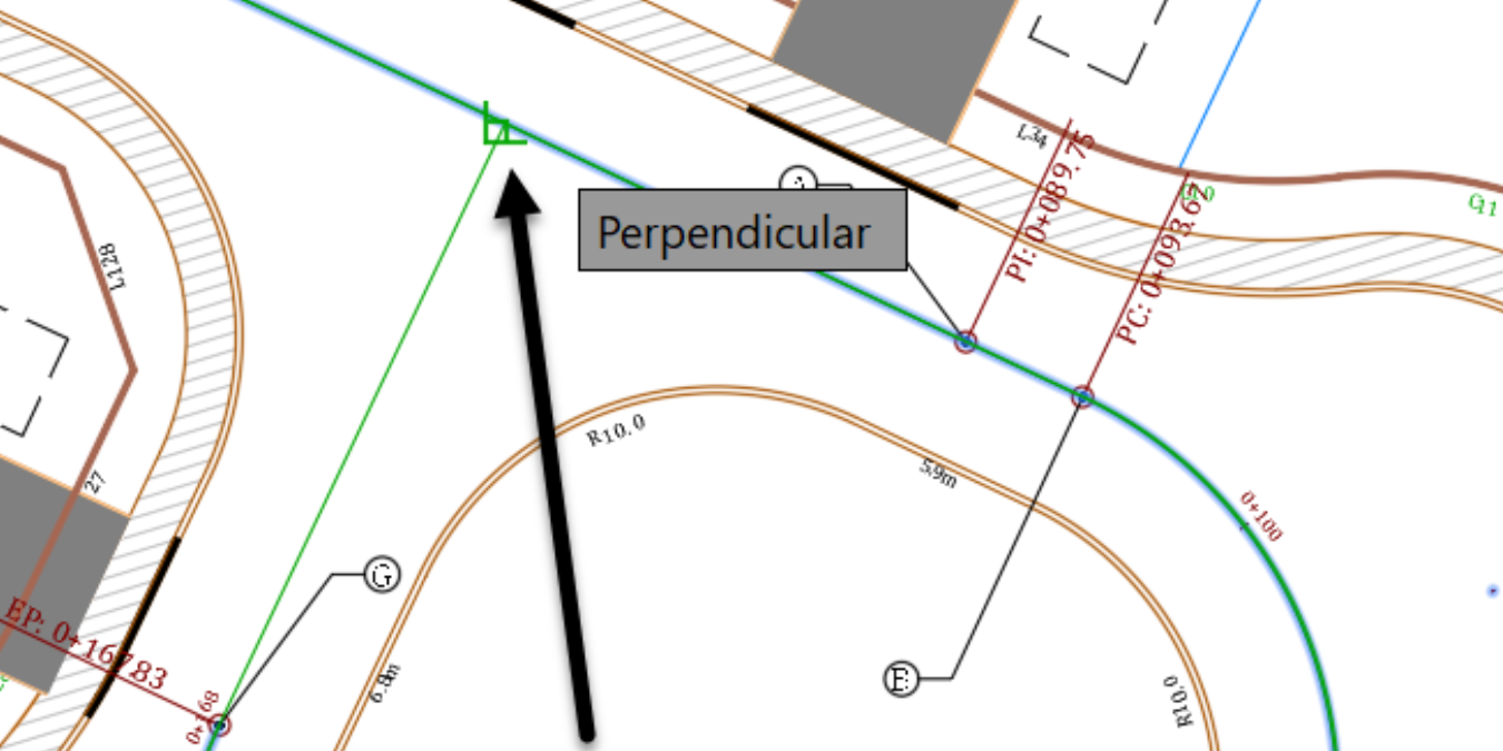
- Last, create a floating line. We could have created a fixed line if we knew the exact location of the start and endpoints. We are going to demonstrate how to use floating lines that always stay tangent to a curve, whatever the circumstances. Run the Floating Line (From curve, through point) command.

- Select the entity to attach to, this time the last curve we created.
- Next, you are prompted for Endpoint. Type PER, an alias for perpendicular, at the command line and press Enter.
![]()
- Move the cursor closer to the first tangent of the alignment. Once you see the perpendicular sign, click on the alignment to snap the new tangent in place.
- Now, let's explore a couple of the Alignment Layout Tools. The first thing we need to do is verify our design through a tabular view. On the Alignment Layout Tools, click on the table icon to the far right.
- The panorama window is displayed. It is used in Civil 3D to display many types of data, such as the Point Editor, the Alignment Entities or other vistas. In this case, it displays the alignment entities.

-
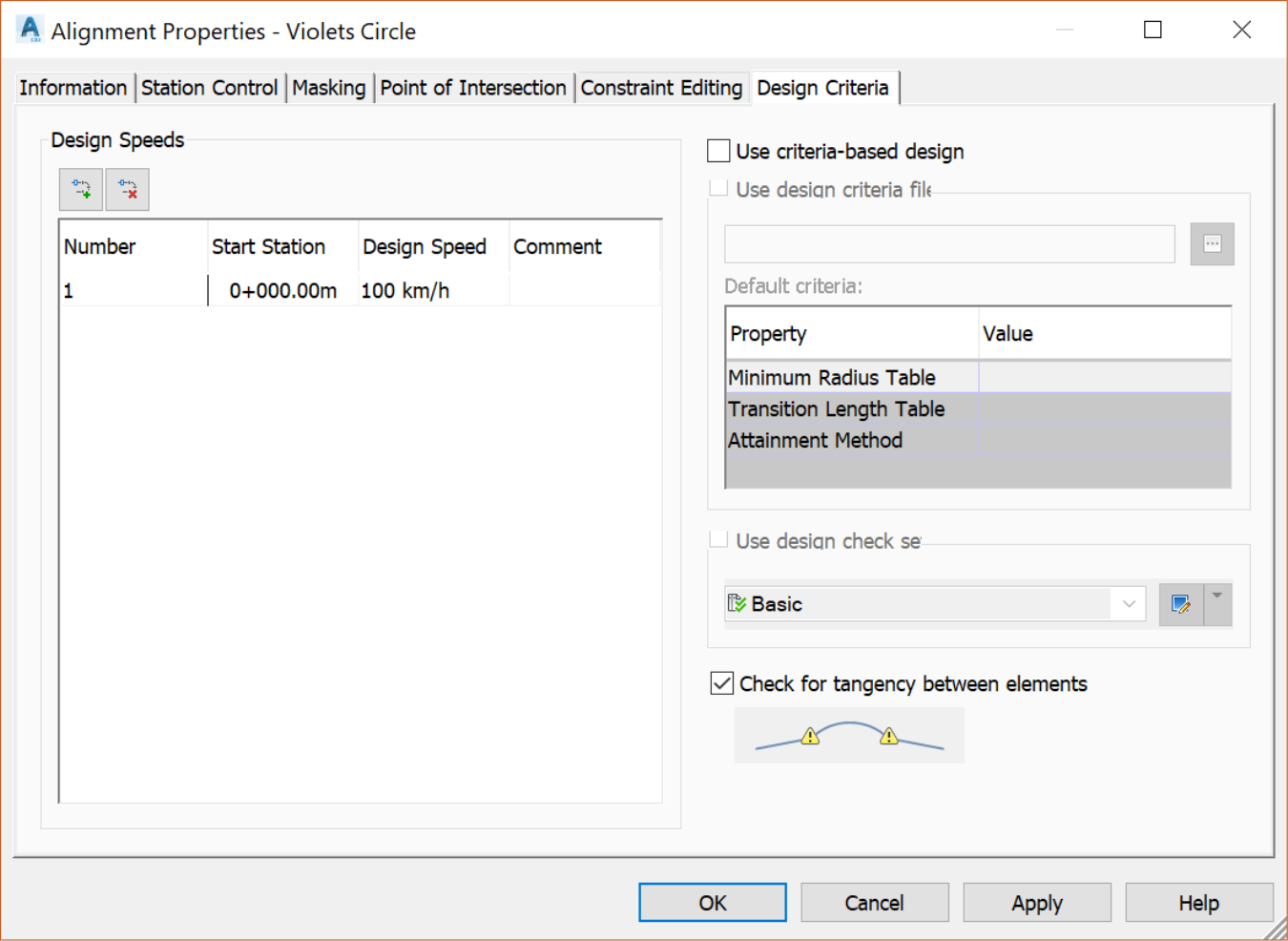
What jumps at us are the warning signs. They represent the sub-entity that violates the specified design criteria. If you were not using a design criteria, you would not have noticed and move along. But since you have applied a design check, violations will be highlighted for you. You have not purposely set the check. It's a setting that came with this specific template and it is activated anytime you create an alignment by using the Civil 3D Alignment by Layout (Alignment creation tools) method. To turn it off,
- select the alignment,
- right click and select Alignment properties
- Then, go to the design criteria tab. On there, you can uncheck the design criteria checkbox. We recommend that you leave it checked. This is just so you know where the error warnings are coming from.
- Now let's fix the warnings. The two culprits are two fixed lines, sandwiching a curve. You can identify them by clicking them in the panorama and watching them getting highlighted in the drawing. As we've mentioned before, Fixed Lines do not always maintain tangency when edited. In a case like this, using floating entities, when possible, is always recommended. To delete the two lines, on the Alignment Layout Tools,run the delete sub-entity command and click on the two fixed lines.
- Once you delete the lines, replace them with floating lines by using the command Floating Line (From curve, through point).
- After that, create the two floating lines and check back in the panorama window. The warning signs are now gone, and everything looks good. In this table, we can check our radiuses, entities directions, start and end stations, and so forth.

- Now, zoom to the intersection of Lavender Court and Rose Drive. Let's say you want to keep things tidy and do not want to have the alignment of Lavender court cross over to the other side of Rose Drive centerline.
- What you can do is insert a PI(Point of Intersection) at the intersection and delete the unwanted excess entity. To do that, use the Civil 3D Alignment by Layout (Alignment creation tools) commands. On this toolbar, let’s mention a few useful tools:
- The Insert PI command used to insert point of intersections

- The Delete PI tool, to remove point of intersections

- The Convert line and arcs tool, to convert AutoCAD entities

- The Reverse sub-entity command to change the direction of a sub-entity

- The Select sub-entity command to select sub-entities for editing

- And the Undo and Redo commands to undo or redo edit operations

