-
Get It
$19.99
$19.99Civil 3D Essentials Book and Practice Files
Civil 3D corridor baseline: A step by step tutorial guide
Introduction to Civil 3D corridor baseline
Firstly, what is a Civil 3D corridor baseline? Well, let's find out in this online training course. Certainly, this step by step tutorial is a part of the Civil 3D essentials book and how-to manuals.
Working with Civil 3D corridor baseline?
- First, click on Add Baseline on the parameters tab.

- We are in a residential neighborhood with straight roads and associated infrastructures. For that reason, the only types of baselines we have are streets. So, select the baseline type of Alignment and Profile and pick Lavender Court for alignment.
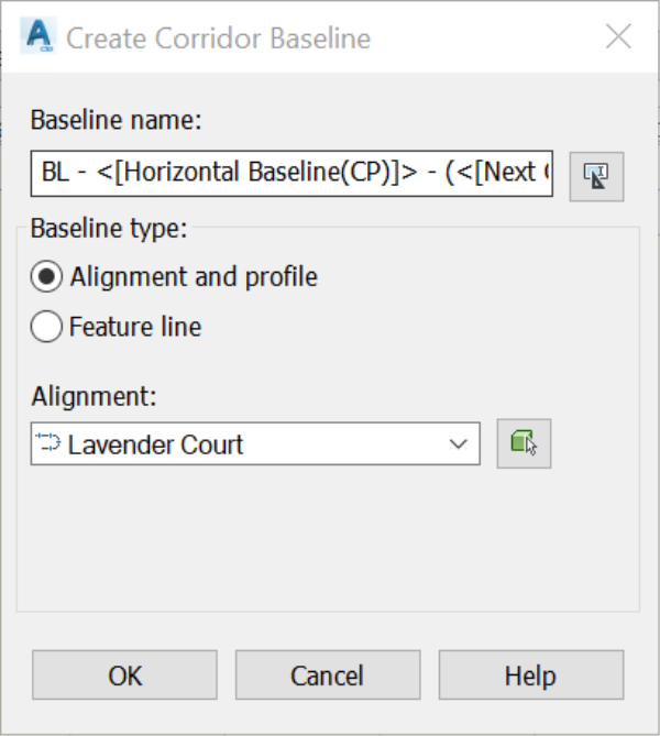
- Click Ok, and you will notice that a new baseline is added to the corridor.

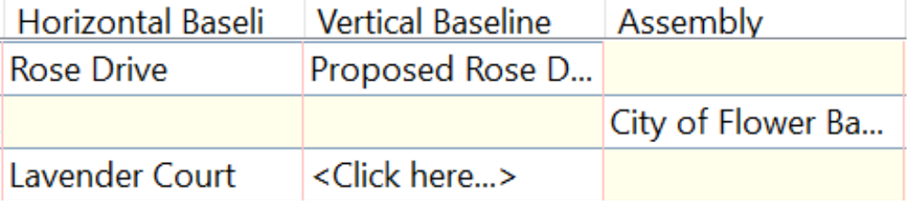
- Now we need to specify the profile associated with the baseline. Click on <Click Here> in the vertical baseline column.
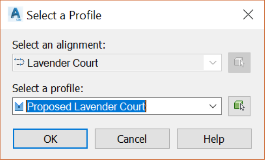
- In the next dialog box, select the Proposed Lavender Court profile and click OK.
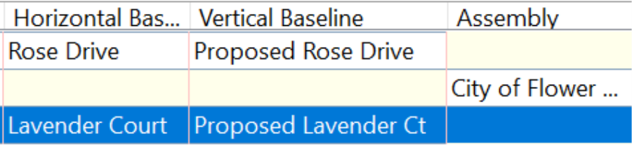
- The new Vertical baseline is added to the corridor.
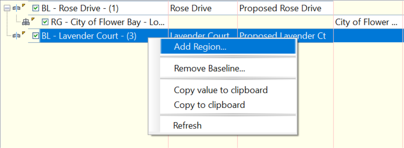
- Next, we need to specify regions, meaning the segment of the road for which we are creating the corridor baseline. To specify the baseline regions, right click on the newly created baseline and select Add Region.
- Next, we need to decide what cross-section to apply in that region of the corridor. One road can have many cross-sections. For instance, think of a project with local roads, major and minor collectors. The Create Corridor Region dialog box would be where we decide which cross-section to use for which part of the corridor. In the current window, select the Local Street assembly. And, frankly, that’s the only one we have created for this project so far. Additionally, it would be nice to name each region and baseline manually, instead of the automated names. But, those names will be good enough since corridors have features to track down regions and baselines.
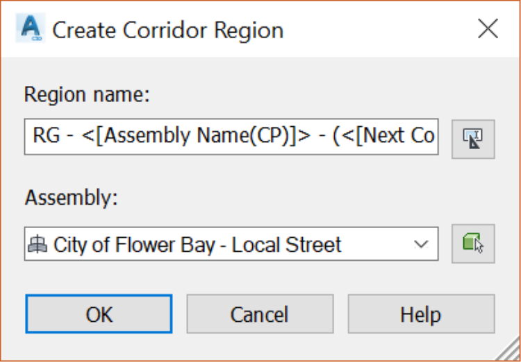
- Click on OK to apply the assembly to the region;
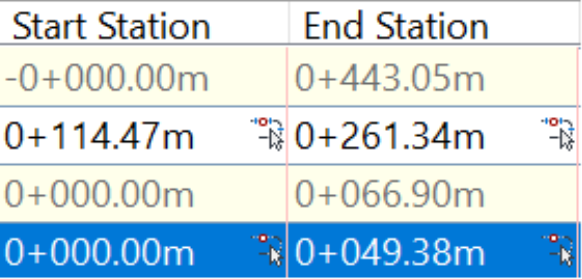
- Make sure you click the “+” sign to the left of the baseline name to expand the list of regions and their information. The Start Station and End Station columns will apply the region range. To provide that information; you can type the station values if you know them. Or, click on the little station symbol
 to the right to specify the station on screen. For the start station, since we know that the alignment starts in the center of the cul-de-sac, accept or type 0+000 for the start station. For the end station, let’s use the symbol option since we have no clue what the exact end station value is. So, click on the little icon, then in the drawing, click on the west end of the curb return. For precision design purposes, activate your end object snap option to click on the exact point of the end of the curve.
- We have now set the start and end of the Lavender Court region. Don’t worry about the yellow warning to the left of the region. It is just a sign that the corridor has changed and needs to be rebuilt. If you don’t have the warning sign, it means that you have automatic rebuilt activated on the corridor, in the prospector.
- Now, click on OK to look at the changes in the drawing.
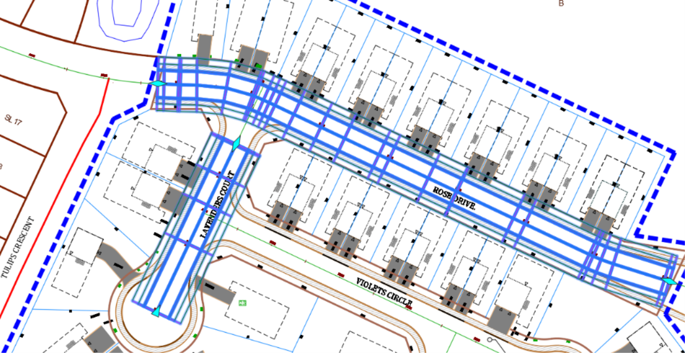
- As expected, we have two regions that extend within the specified stations.