-
Get It
$19.99
$19.99Civil 3D Essentials Book and Practice Files
Civil 3D Corridor Creation: A step by step tutorial guide
Introduction to Civil 3D Corridor Creation
Firstly, how easy is a Civil 3D Corridor Creation? Well, let's find out in this online training course. Certainly, this step by step tutorial is a part of the Civil 3D essentials book and how-to manuals.
Starting Civil 3D Corridor Creation?
We are often challenged with creating 3D models to make a flexible and advanced representation of our design. Civil 3D corridors allow us to create these models for design projects such as roadways, highways, railways and more.
The corridor creation brings together various Civil 3D components and integrates them into one monolithic 3D model. The three most basic constituents for a corridor are:
- an alignment or baseline,
- a profile, sometimes substituted by a feature line,
- a 2D cross-section of the entity being modeled, represented by an assembly.
Other Civil 3D objects and data can also contribute to the creation of a more complex and robust corridor model. Among others, we can use polylines, surfaces, and profiles to improve a corridor.
Corridors are not typically printed on construction plans unless elaborate styles and code sets are used. However, they can be utilized to extract invaluable data. That includes points, surfaces for volume calculations, feature lines for grading, and many more.
Practicing Civil 3D Corridor Creation?
Now that we have the three required basic elements (alignment, profile, and cross-section) for the corridor creation, we can create a road model or corridor. To do that:
- Click the CorridorCreation command, on the ribbon, in the Create Design Panel of the Home tab.
-
In the next window, define the following parameters for the creation of the corridor:
- For the corridor creation, first, assign a name to the corridor. Call it Corridor - Rose Drive, for example;
- Then, enter the description: even though not necessary, it builds a good habit to always enter descriptions;
- For the style, let’s go with the basic style. The style displays the appearance of the corridor components. Including boundaries and assembly insertion stations;
- Next, leave the layer to the default layerassignedin the template;
- The corridor elevations can be built either from profiles or Feature lines. When possible, always use alignment and profile. You can, later, use them to create road sheets and other construction plan items.
- For the profile, choose Proposed Rose Drive. Don’t worry if there is a number in the bracket after the name of the profile. That simply indicates the number of times the profile has been created in this file.
- For assembly, pick the City of Flower Bay – Local Street typical section.
- Next, pick Existing Ground as the target surface. We don’t really need one in this case since we are leaving the road unfinished at the property line.
- Finally, uncheck set baseline and region parameters. We will come back later to the Baseline and Region Parameters dialog box. It will allow us to specify parameters such as baselines, regions, targets, frequencies, and much more. This is the main corridor setup and edit window.
- Lastly, click OK.

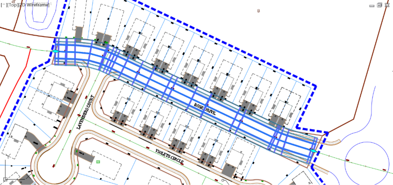
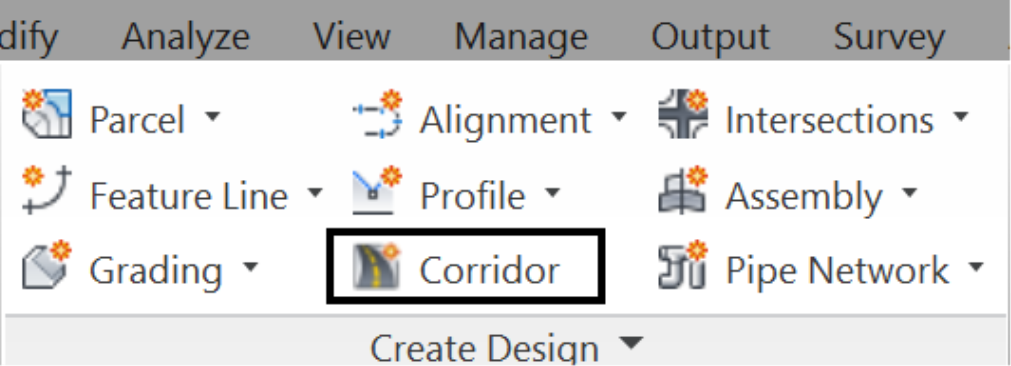
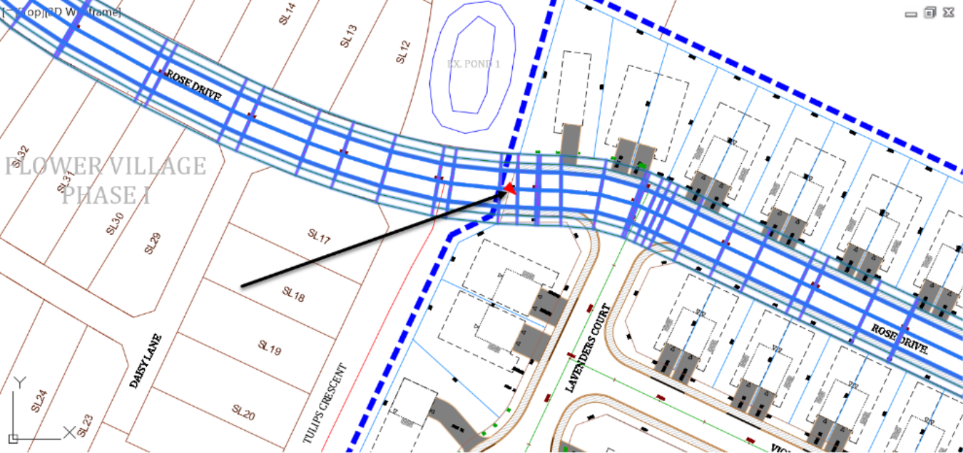
- If you zoom to the Rose Drive road area, you will notice that the corridor has now been created. It extends further than needed, to the previous phase of the project to the west and to undeveloped lands to the east. This is simply because we haven’t set any parameters when creating the corridor, so it simply defaults to the full length of the alignment.
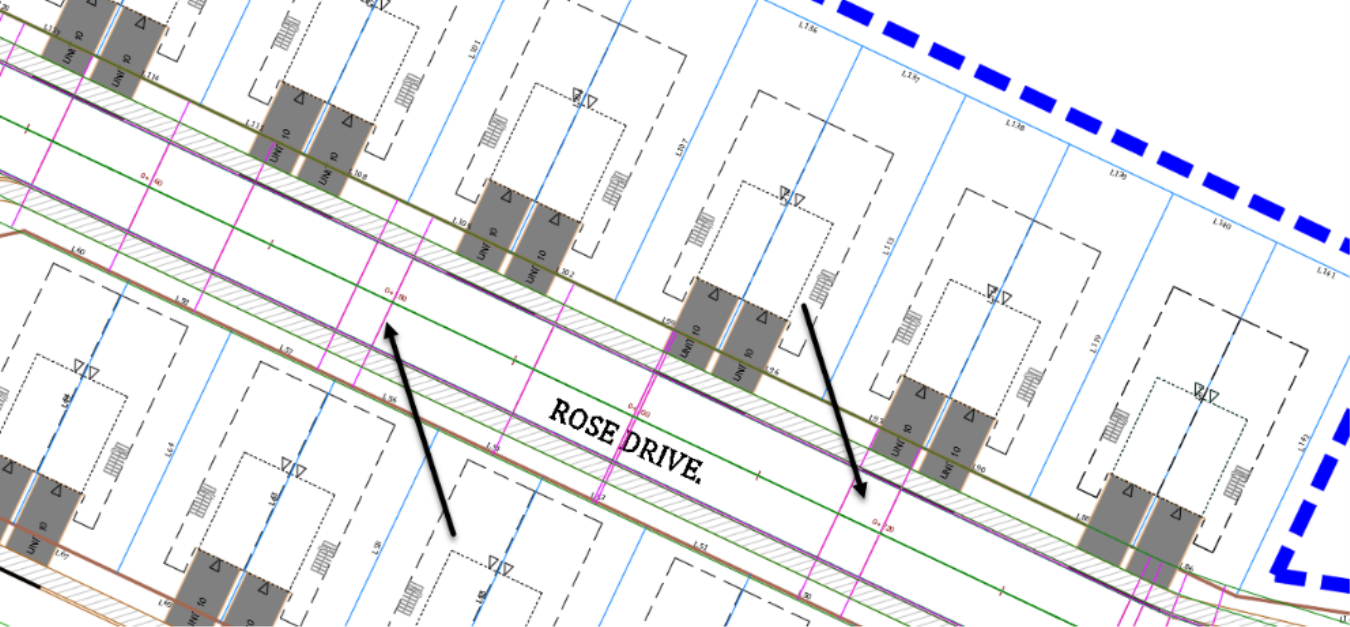
- Now, zoom to the west end of the corridor. When you select it, you will notice a cyan grip triangle shape at the end.
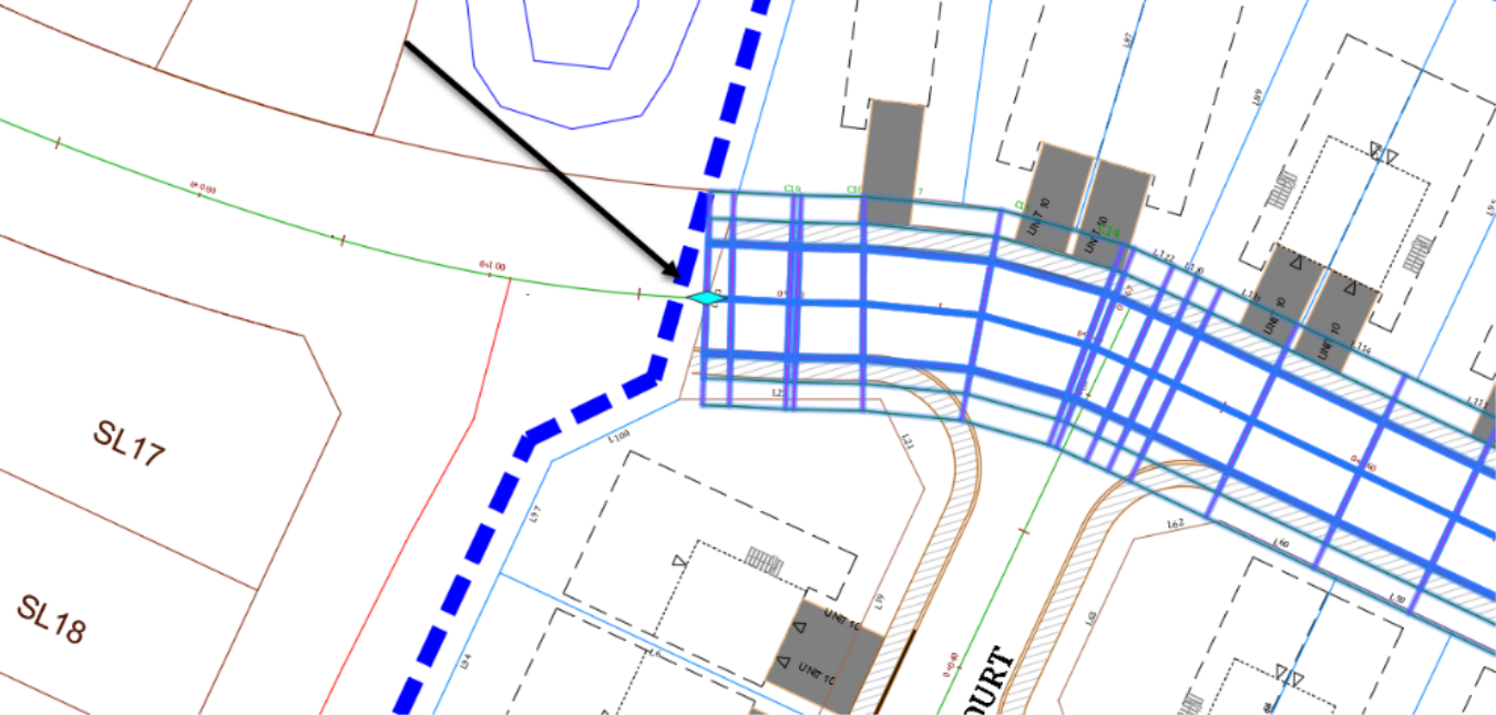
- Then, grab it and slide slowly eastward, all the way to the start of the current phase of the project and click at the site boundary line.
- The west limit of the corridor is now at the site boundary. You will notice that the triangle is now a diamond shape, which means we can extend it in either direction.
- Finally, repeat the same previous steps and move the east corridor limit to the east site boundary line, just before the roundabout. The corridor is now contained within the site boundaries.