-
Get It
$19.99
$19.99Civil 3D Essentials Book and Practice Files
Civil 3D corridor Surface: A step by step tutorial guide
Introduction to Civil 3D corridor Surface
Firstly, what is a Civil 3D corridor Surface? Well, let's find out in this online training course. Certainly, this step by step tutorial is a part of the Civil 3D essentials book and how-to manuals.
Working with Civil 3D corridor Surface
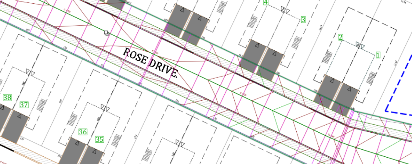
One of the best utilization of a corridor is that we can use it to generate a surface. The corridor surface can then be used or combined with other design elements to create a final ground surface. In can also help compute earthworks quantities or be exported for field stakeout, for example. Corridor surfaces remain dynamically linked to the original corridor. They will be updated if the corridor changes. Like any other type of surface, a corridor surface will also appear in the surface collection of the prospector. There, you can change its style, label it, or use it for surface analysis.
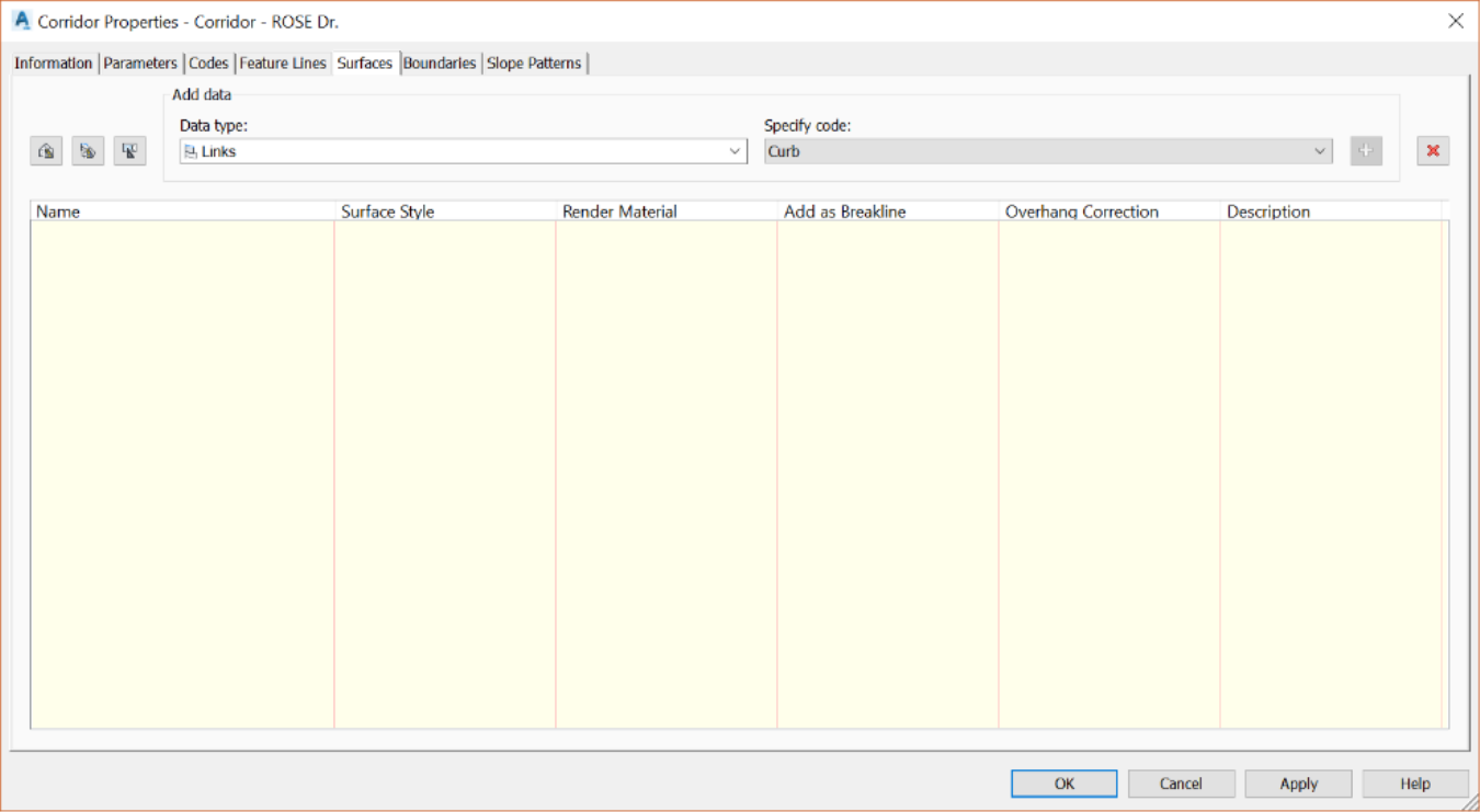
- The corridor surface is created using the Surfaces tab of the Corridor Properties dialog box.
-
As shown in the data type drop-down box, two types of corridor elements can be used to create a corridor surface:
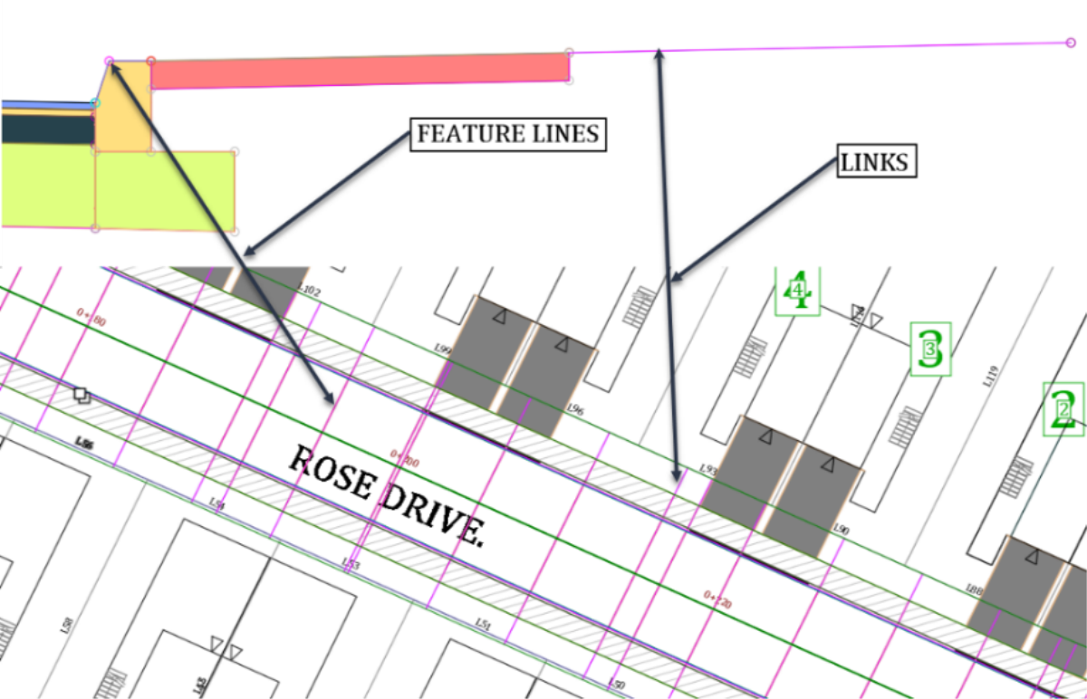
- Links, which are the linear objects in the assembly like the lane, curbs or sidewalks, and
- Feature lines, which represent the point objects such as road crowns, curb tops or backs, in the assembly. These point objects are converted to lines in the plan view of the corridor.
-
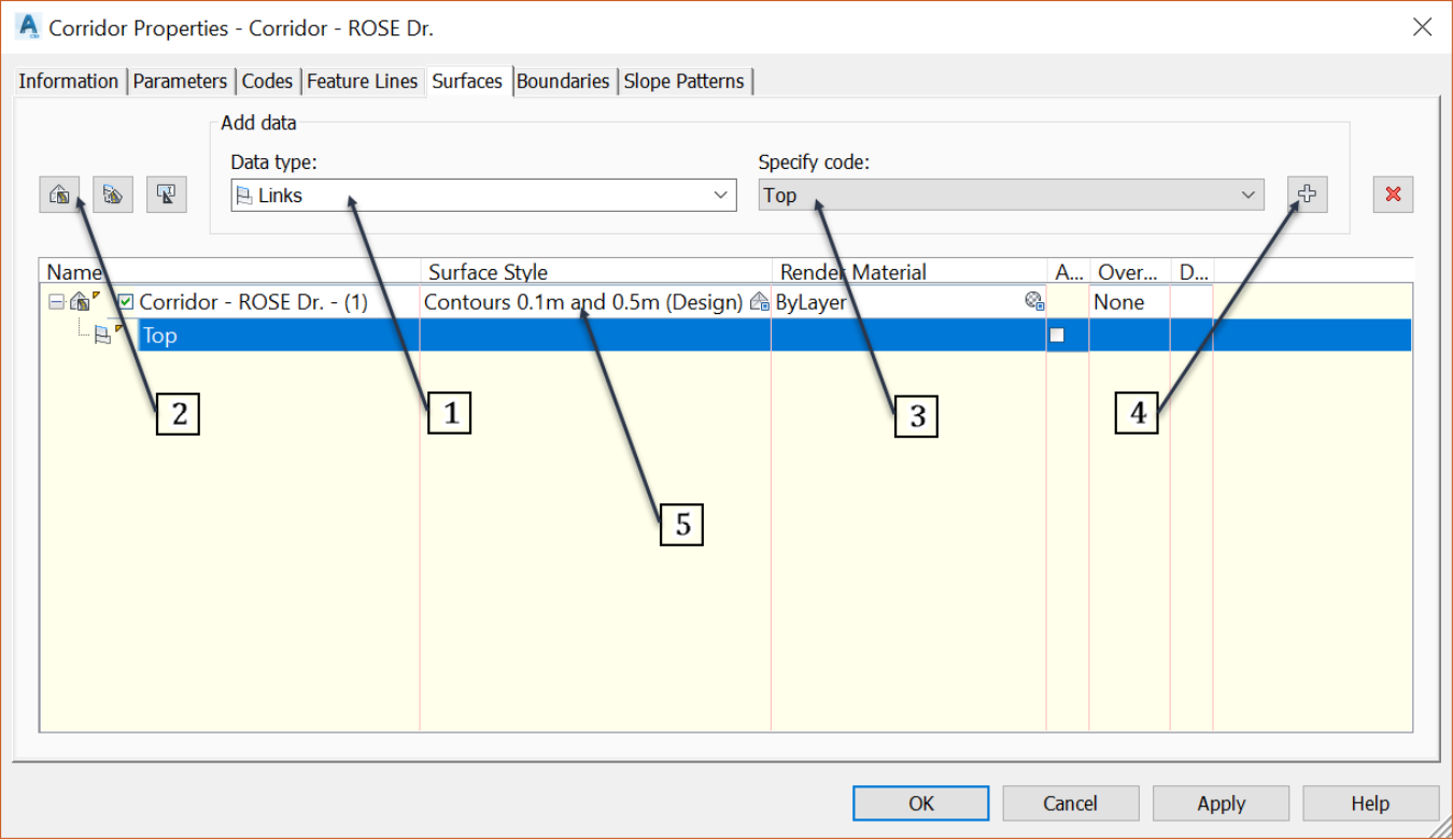
Let’s use the Links method to extract a surface from a set of link codes. Since we are looking to create a finished ground surface, we will use the Top link code. This code is included in all superficial points such as lane crowns, the top edge of pavements, face and back of curbs, top of sidewalks and generic links. If we needed to create a base or subbase surface, we would just use the links with codes including the base or subbase. To create the top surface,
- Click on the create a corridor surface command,
- specify a Top code,
- then click on the “+” button to add the surface definition and choose a Surface Style.
- Since this is a relatively flat road surface, we will choose a dense contour style, like the 0.1m or 0.5ft minor contours.
- Once the surface has been defined, next we need to specify a boundary. Due to the triangulation between cross-sections, corridor surfaces tend to extend beyond the roadway area. To force the surface to stay within the road right of way, we must define a corridor boundary. To do that, switch to the Boundaries tab, then right-click on the surface name and choose to add the Corridor extents as an outer boundary. That adds the boundary automatically from the corridor extents. This option is most adequate for a corridor with many baselines, such as ours. When dealing with a single baseline corridor, it would be better to add a boundary from <code name>. An example of sample codes isETW - Edge of Travel Way or P2 for generic assembly codes.

- Optionally, we can also add boundaries interactively by clicking on the drawing. We can also select the Polygon option and click on a pre-existing closed polyline.
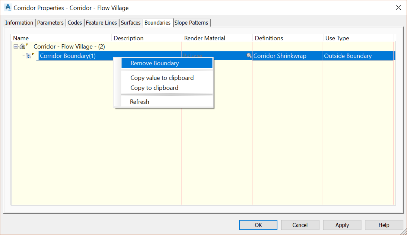
- If you ever need to remove a corridor surface boundary, simply select it, right-click and select remove boundary. We will not do that in this case, since we need the corridor boundary.
- Now, click OK to close the corridor properties dialog box. You will notice that a corridor surface is created and displayed in the drawing area. Furthermore, it is bounded to the street right of way.