-
Get It
$19.99
$19.99Civil 3D Essentials Book and Practice Files
Civil 3D Corridor targets: A step by step tutorial guide
Introduction to Civil 3D Corridor targets
Firstly, what are a Civil 3D Corridor targets? Well, let's find out in this online training course. Certainly, this step by step tutorial is a part of the Civil 3D essentials book and how-to manuals.
Working with Civil 3D Corridor targets?
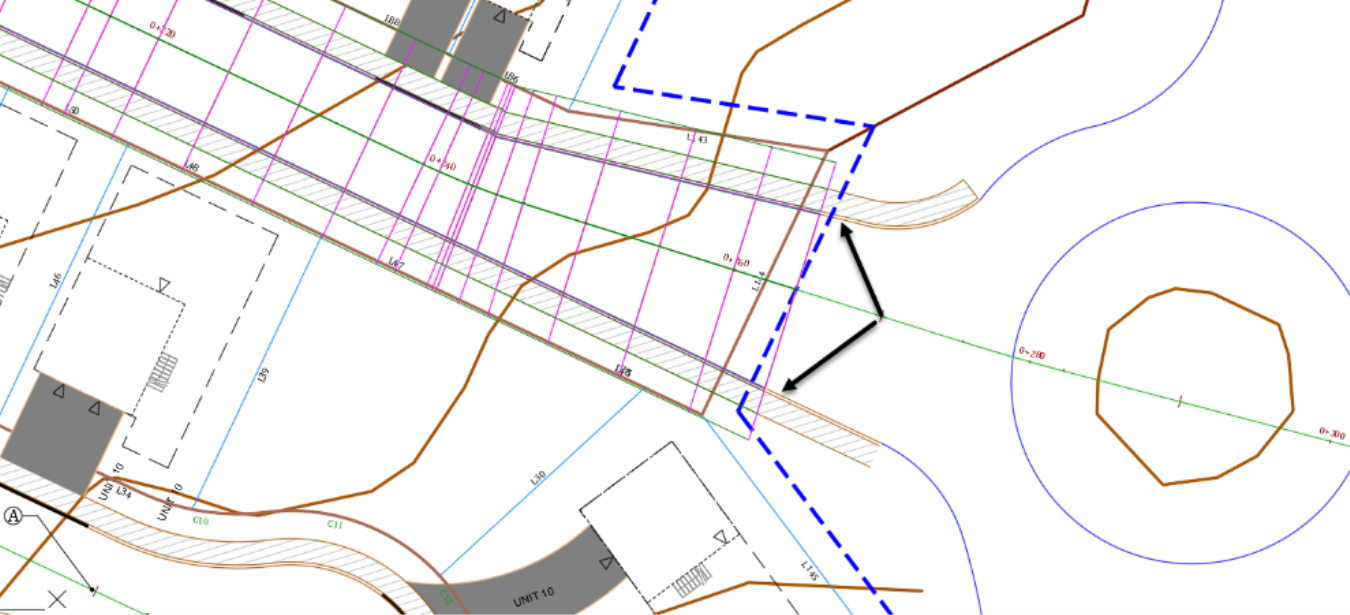
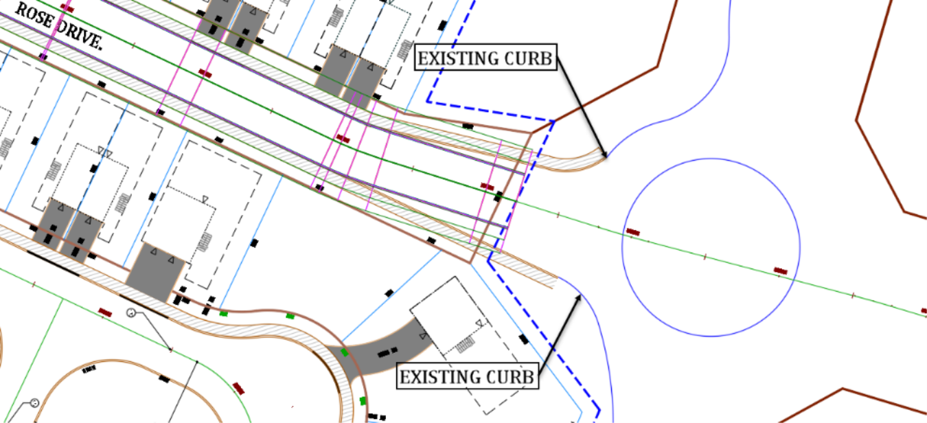
After baselines and frequencies, the third type of parameter we can manage are targets. As a reminder, targets enable us to connect to existing features, either by offset, elevation or projection to a surface. In this project, we have an existing curb and pavement that we need to tie to. But, the existing and proposed pavements don’t necessarily have the same width.
For that reason, our street needs to widen to match the existing road.
- To widen the road to match the existing pavement, we need to apply the target parameters of the corridor. Return to the Corridor Properties window.
- Click on Set All Targets on the Parameters window.

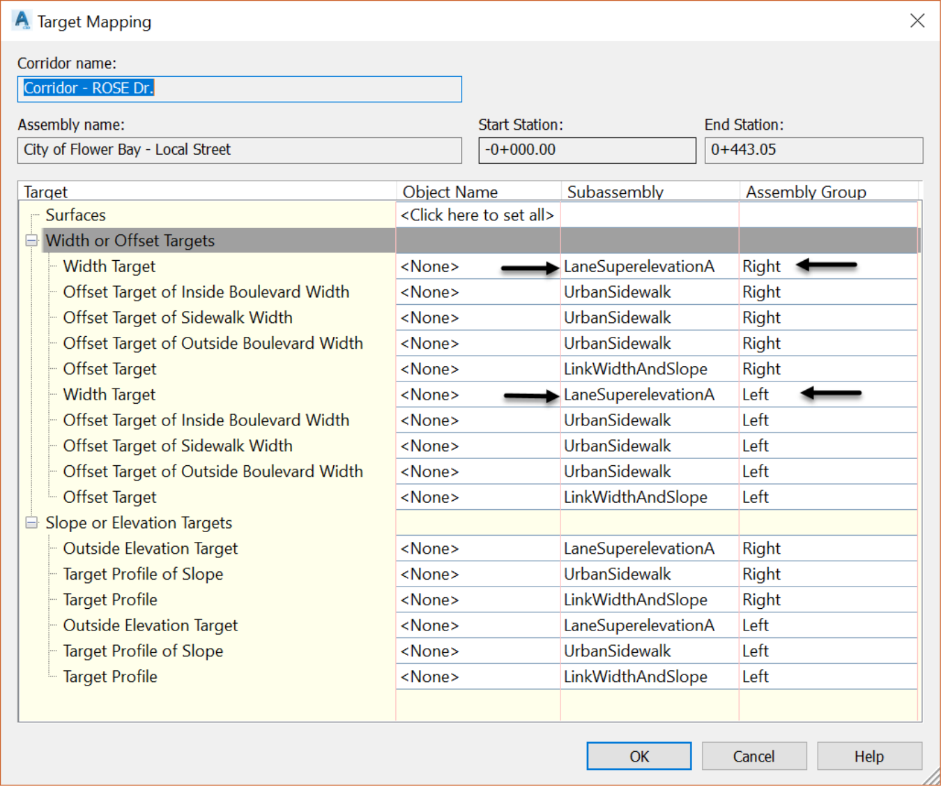
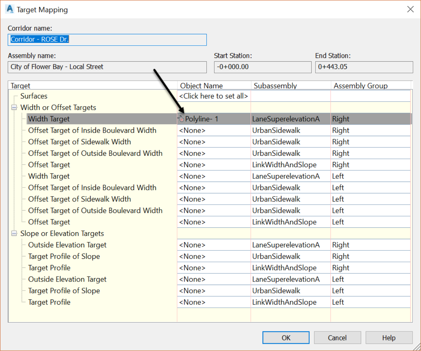
- On the Target Mapping dialog box, we can set the three types of targets we’ve mentioned before: Surface, Width or Offset and Slope or Elevation.
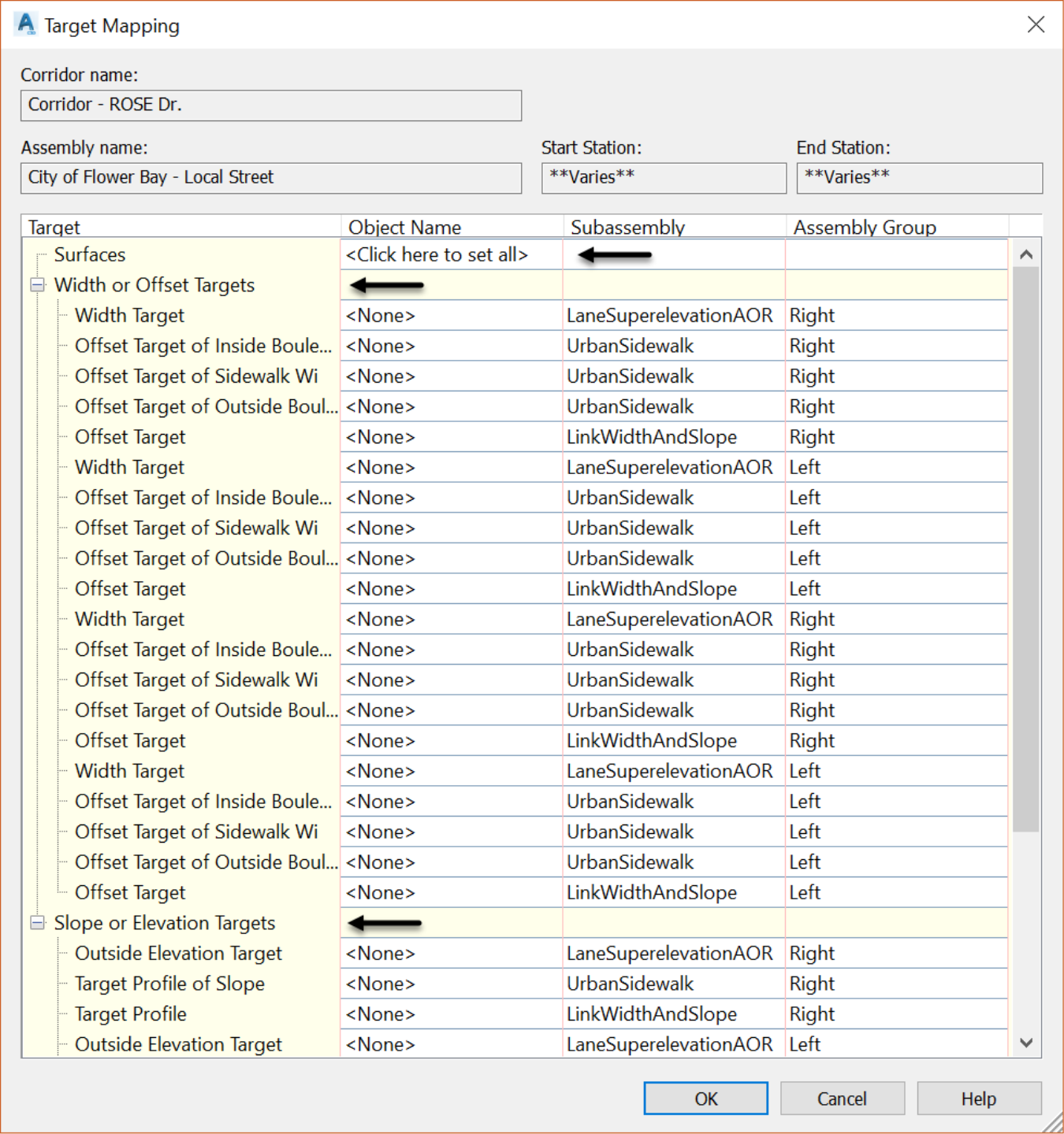
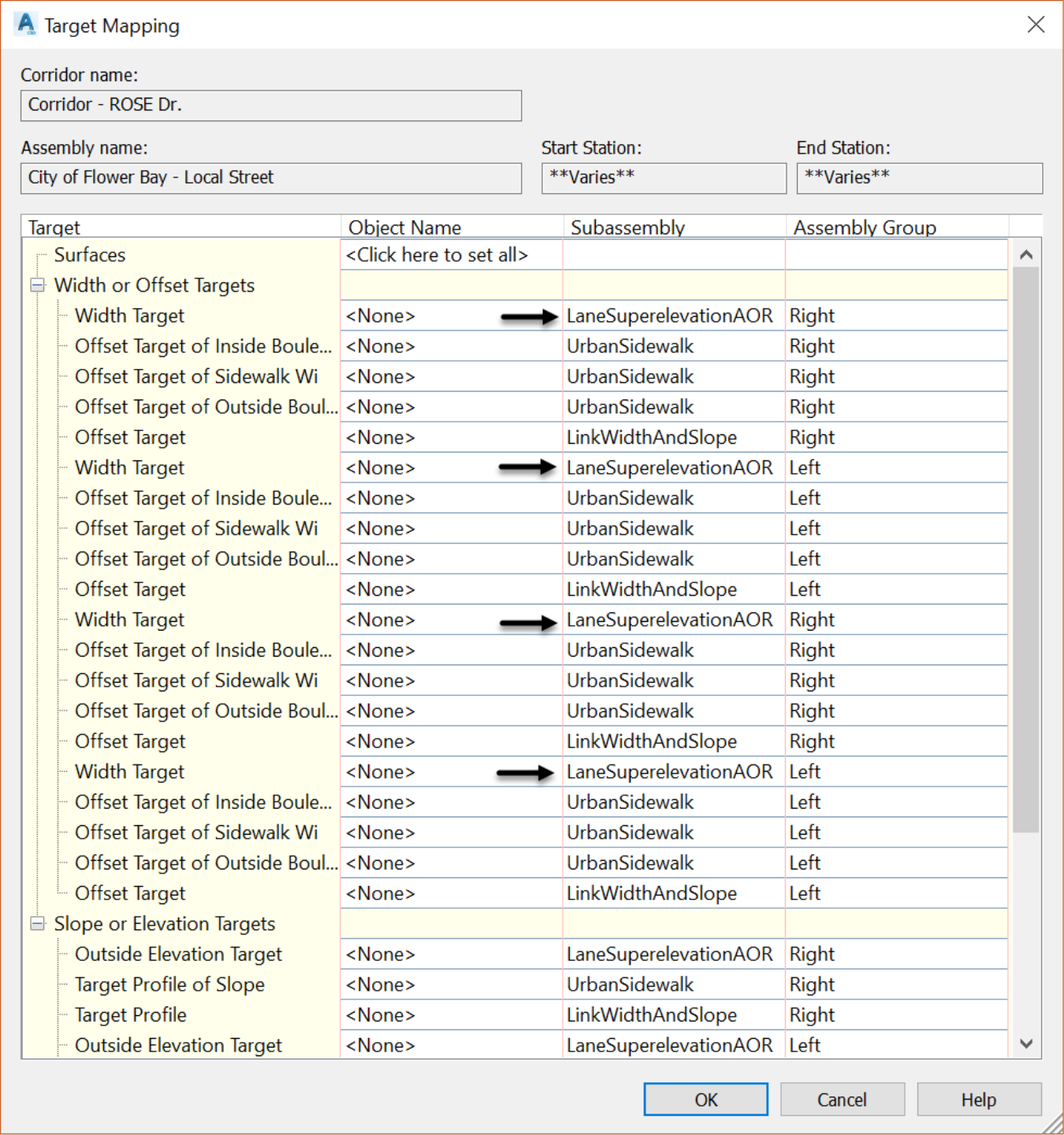
- We have no options to choose in the surface section because we have not used any subassembly that can target a surface. We are mostly interested in the width target in this case. The item that needs to be extended is the road pavement. It is represented by the LaneSuperelevationAOR subassembly. Scroll through the width or Offsettarget section. You will notice that the LaneSuperelevationAOR subassembly is on four lines.
- So, what we are going to do is back up a little bit and return to the previous window, to pick where we would like to apply the widening. Click on OK or Cancel to close this window.
- Now, go back to the corridor Parameters tab, in the Target column. Click on the icon with the three dots on the Rose Drive Baseline or RG – City of Flower Bay region. Choosing Baseline will apply the target to the whole baseline while choosing a region will apply the target only to that specific region.
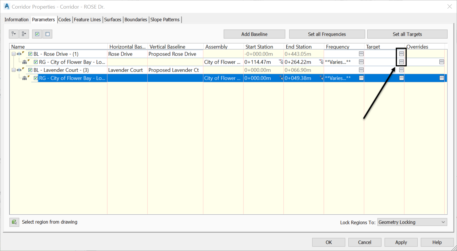
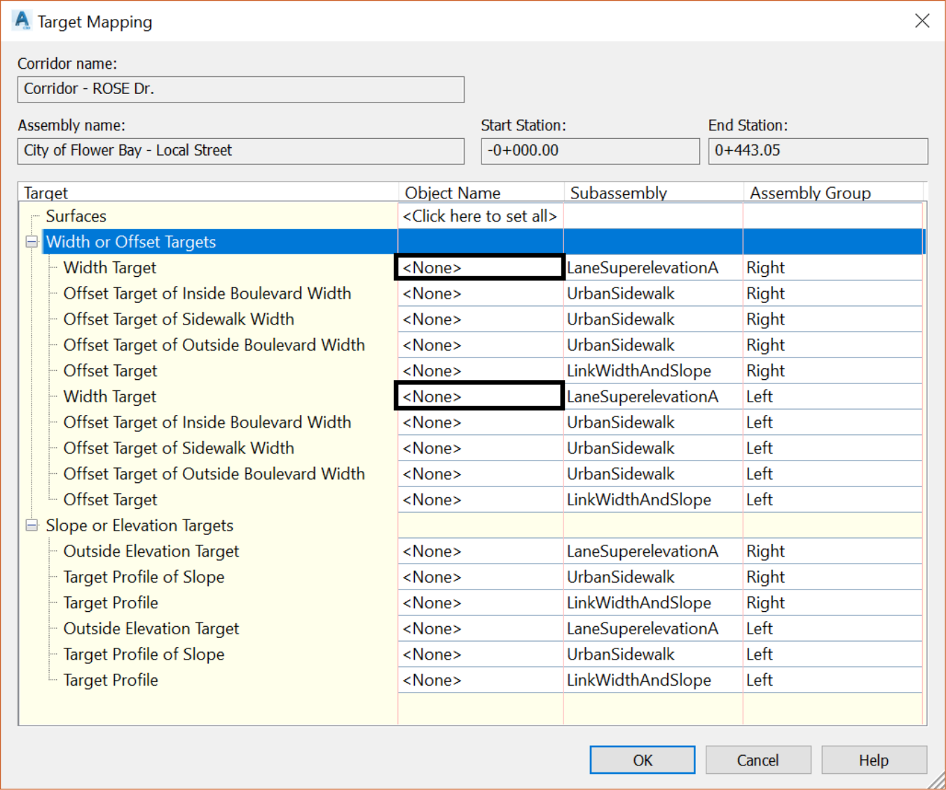
- Let’s go with the entire baseline icon, the top one. Once you clicked on that, the same previous Target Mapping window opens. But, this time with much less data, because we chose to only work with the Rose Drive baseline. Consequently, we only have two lanes to work with. The left and right sides of the road.
- On each of the two LaneSuperelevationAOR lines, click on <None> in the Object Name column. Before clicking on each, make a note of which side, left or right, you are working on from the Assembly Group column.
- In the new Set Width or Offset Target window, change the object type to Feature Lines, survey figures and polylines and click on select from drawing.

- In the drawing, for the left-side lane, click on the north face of the curb polyline, and for the right-side lane, click on the south face of the curb polyline.
- Once a polyline is selected, it will automatically appear in the Selected entities to target list.

- Once you click OK again, the selected polyline will appear in the Object Name column.
- Repeat the same steps for the left side of the road, by picking this time the north face of the curb polyline. Once done, you should have something like the right side, with a new name.
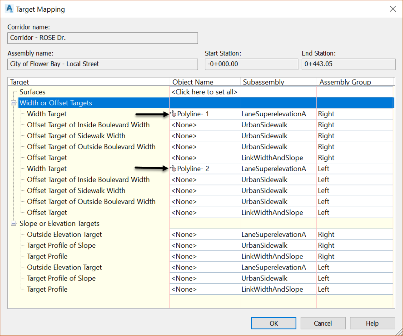
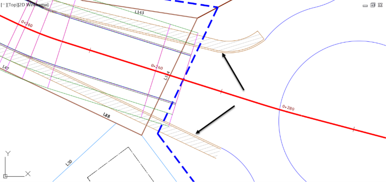
- Click OK to close the Target Mapping window. In the drawing, notice how the road widens to match the existing pavement.