-
Get It
$19.99
$19.99Civil 3D Essentials Book and Practice Files
Civil 3D cross-section, assembly and subassembly : A step by step tutorial guide
Introduction to Civil 3D cross-section, assembly and subassembly
Firstly, what is a Civil 3D cross-section, assembly, and subassembly? Well, let's find out in this online training course. Certainly, this step by step tutorial is a part of the Civil 3D essentials book and how-to manuals.
Working with Civil 3D cross-section, assembly, and subassembly?
The assembly represents the cross-section of a given right of way. A typical section is almost always provided in the design manual by the permitting agency. Civil 3D provides us with tools called subassemblies. They can be leveraged to represent the components of a typical cross-section such as travel lanes, curbs, and sidewalks. We have recreated and will show later, the typical cross-section requirement for the municipality of Flower Bay. For a local minor road, like the ones in our subdivision, the requirements can be as follows:
- A travel lane width of 3.5m or 11.5ft on both sides of the road centerline, at 2.5% slope, followed by a 20centimeter or 6in straight curb.
- Then, an abutting 1.5m or 5ft sidewalk, at a 2% slope.
- Finally, a 1.8m or 6ft, at 2% landscaping strip, extending to the property line.
In addition, we must also meet the underground utility depth and separation requirements.
Once again, let’s summarize. To create a corridor we need: a baseline or alignment, a feature line or profile and a typical cross-section or assembly.
So far, we have created the first two. Now, let's see how to create the typical cross-section, or an assembly, in Civil 3D parlance.
- To begin, open the 09.01-Corridors dwg file in Lesson 09 practice folder.
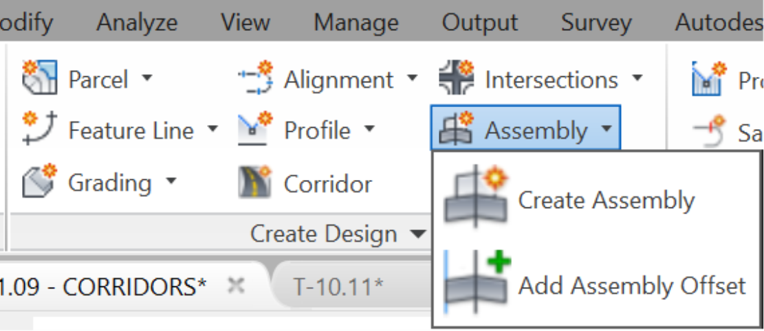
- Next, from the Home tab, on the Create Design panel, launch the Create Assembly command.
- Then, give the assembly a name that indicates the situation in which it will be used. For example, call it City of Flower Bay Local Street. In the next window, you can,
- First, give an optional description of the assembly.
- Then, specify the type of roadway that the assembly will support. For example, we may wish to apply the calculation of superelevation for the axis of rotation. Therefore, the assembly type must match the Roadway Type, on the superelevation calculation page. For the current project, we will not need any of that, since we are not creating any superelevation. Nonetheless, let’s choosetheUndivided the Crowned Road type.
- Afterward, specify an assembly Style like we assigned an object style to the Civil 3d objects we have previously seen.
- Then, you have the Code Set Style, which will determine the styles of the different components of the corridors, like points, lines, and areas. This is different from the assembly style, which once again creates a style for the cross-section. We will better understand the difference in a moment when we see them in action.
-
Next thing you can do is choose an Assembly Layer, which we will leave to the template to assign for us, by default.

- Press Ok to exit the Create Assembly dialog box.
- In an empty area of the screen, choose the insertion point of the Assembly. How the assembly appears (brown line with a magenta circle) is decided by the Assembly Style. Now we know what the assembly style we chose means. We can always right-click on it to edit the style to our liking.

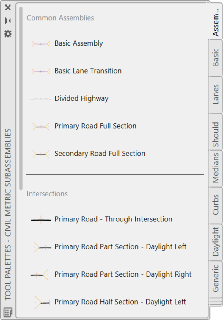
- Once the assembly is created, we need to attach the sub-assemblies to it. They are the different elements that make up the cross-section. To create sub-assemblies, click on the Tool palettes (this is different from the Toolbox that is part of the prospector).

- The Tool palette opens:
- Now, display the Properties window, if it is not already opened.

- Then, you need to organize your work environment in such a way that you can easily access your different windows and palettes. For example, place the Properties Window on the right, and the Tool Palettes to the left. An ideal Civil 3D setup would be to have at least two monitors and distribute the windows for easy access.

- Once the Tool palettes are displayed, you can start creating the subassemblies. Just remember that we are creating an assembly per our design requirements.

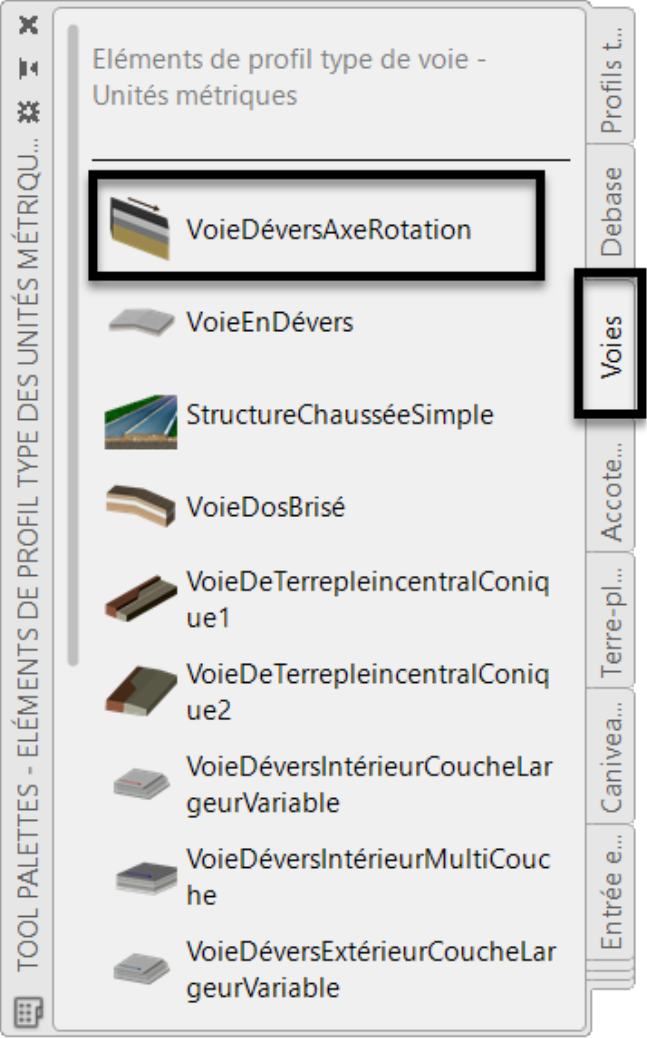
- Let’s start from the centerline and work our way out to the edges. On the Tool Palettes, click the Lanes tab.

- Click on LaneSuperelevationAOR. This is a general and versatile lane subassembly because it can be applied for Outside or Inside Lane superelevation slopes. It can also be used for divided, undivided, crowned and broken-back roads. Furthermore, it offers up to four layers for the pavement structure. Most of the time, this would be the only Lane subassembly you will need for local streets.
-
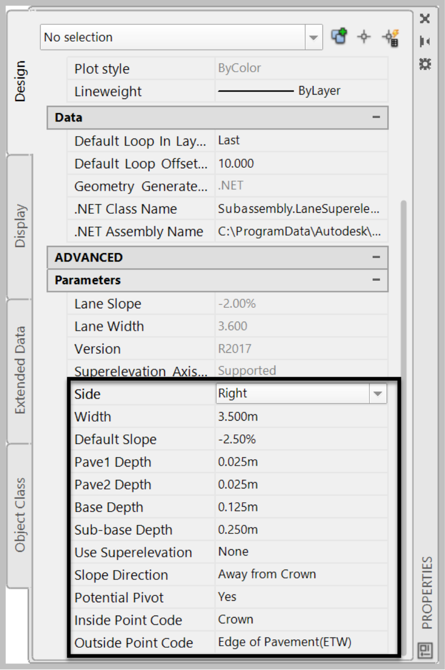
Now, we are going to apply our specifications to this subassembly. Once you clicked on it, you will see that the properties window already took notice and displayed all the parameters for this subassembly. In the Properties window, scroll down to the Parameters sectionand enter the following values:
- 3.5 meters or 11.5ft for Width;
- -2.5 % for Default Slope;
- 0.050m or 0.15ft for Pave1 Depth. This will be the first lift of asphalt;
- 0.050m or 0.15ft for Pave2 Depth. That is for the second lift of asphalt;
- 0.125m or 0.40ft for Base Depth, for your granular base material;
- And finally, 0.250m or 0.80ft for Sub-base Depth, the road sub-base material;
- Before moving to the next step, notice the line that says Side. You can change it to the left or right. That means that any subassembly that we select will be inserted on the side that we chose. So, we need to be mindful of that.
- Click on the circle of the cross-section.
- At this point, our right lane has been placed.
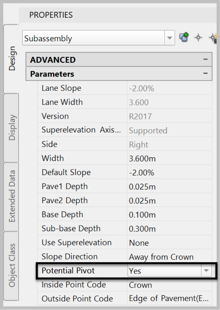
- Since we are designing a subdivision street without any need to create a superelevation, we are going to turn off the options to pivot the lane. Select the LaneSuperelevationAOR subassembly. Then in the Properties Window, in the Parameters section, find the Potential Pivot line and change it to No.
- Next, we need to create a straight face curb abutting the lane. Our curb will have a 0.15m or 6in height of a curb and a 0.20m or 0.5ftwide back of curb. To create the curb,
- We can either use the BasicCurb on the Basic tab of the Tool Palettes, which works in this case since our curb is a basic one. Or,
- You can switch to the Curbs tab of the Tool Palettes and choose a more advanced one, depending on your situation. To demonstrate how to customize the curbs, let’s use one of the advanced ones.
- On the Curbs tab, click on UrbanCurbGutterGeneral.

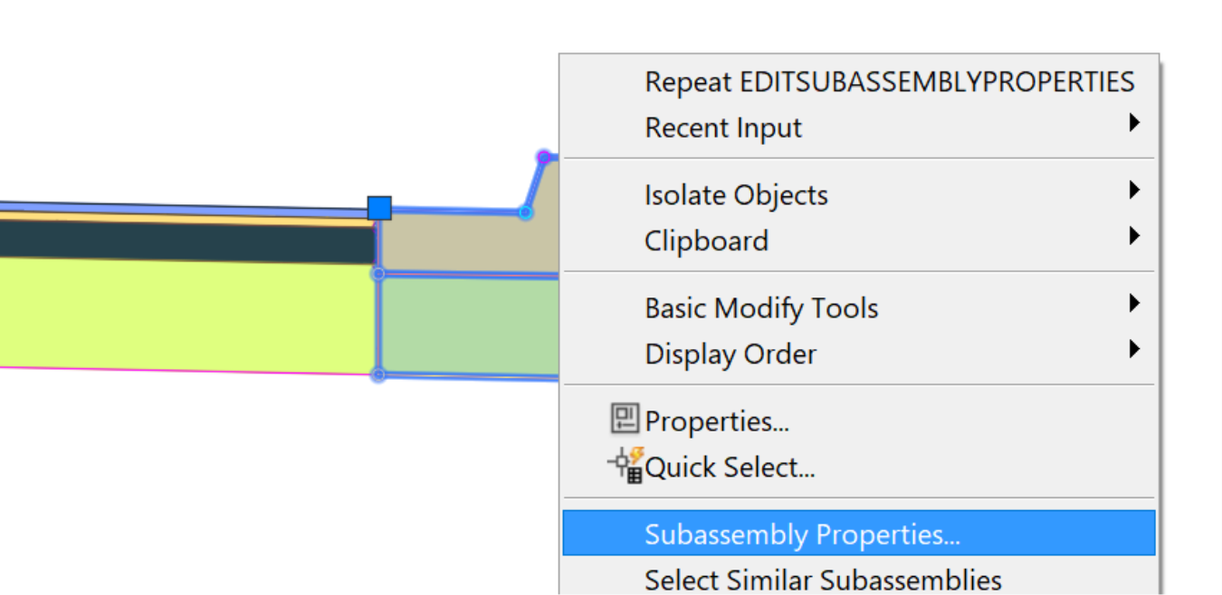
- Next, we need to specify the parameters of the curb and its attachment point. Before entering the parameters, we first need to understand what the different values mean. For that, we can call the Subassembly help for assistance. Select the curb subassembly, right-click and select Subassembly Properties.
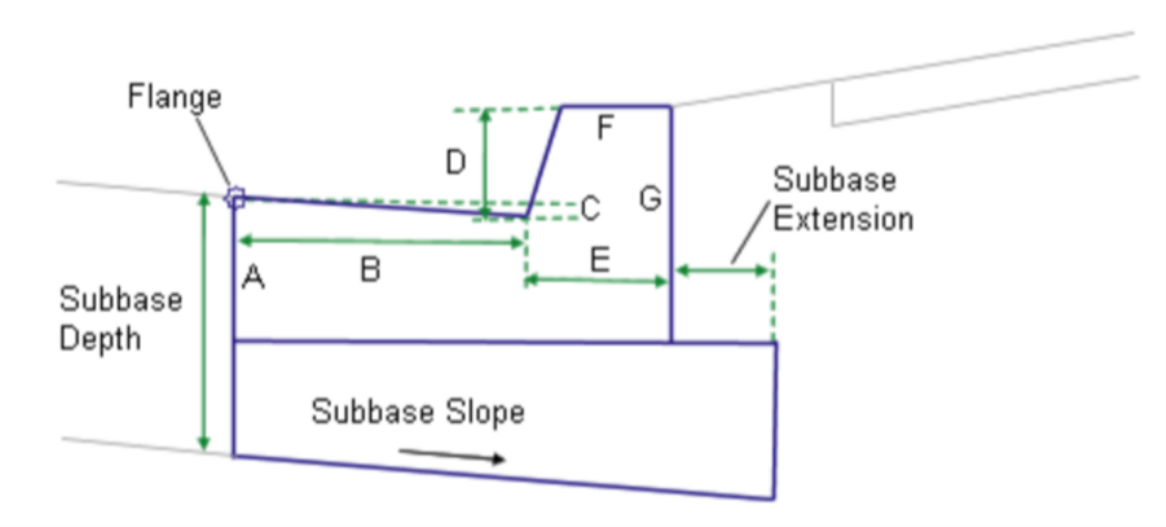
- In the next window, activate the Parameters tab and click on Subassembly Help.

- The figure displayed explains the required values in the parameters section of the property window.
- Now, keep the help window open, maybe on a second screen if you have one, and click OK on the subassembly Properties windowto return to the drawing. In the Properties window, while you have the curb selected, adjust the following parameters.
- Dimension B (in millimeters or inches) which represents the Width from the flange point to the gutter flowline. This is typically for a road with a curb and gutter. Since we don’t have a gutter, you are probably thinking “we should just put zero.” Unfortunately, Civil 3D will not accept that. So, we need to trick it and put a microscopic value, say 0.001. This will not make any difference in real life. Besides, this is to show how to use the subassemblies and adjust them to your needs. Now, the subassembly appears without a gutter.
- Next, we need to make sure that Dimension D (0.15m or 6in) and dimension E (0.20m or 8in) meet our requirements, which they do by default. We also have a Sub-base meeting our requirements. Notice that we have changed the slope of the face of the curb. If it is absolutely required to have it at a 90 degrees angle, we can simply use the basic curb. There are also Civil 3D tools such as Subassembly from Polyline or the Subassembly Composer we can use to meet unique design conditions. We refer you to Infratech’s Advanced Road Design course for more on these tools. For now, the only thing left is to change the Sub-base slope of the curb to 2.5%, and we are all set.
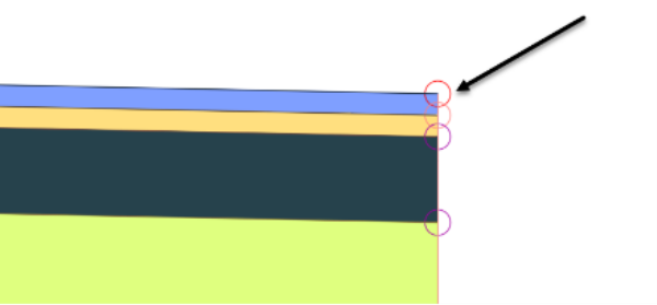
- Next, we need to specify the attachment point of the curb. For that, click on the upper circle of the right edge of the lane. Note that we can also first specify the attachment point of the subassembly and then adjust the parameters as needed.
- After the curb, we now need to specify the parameters of the sidewalk. Here, we also have two options. We can either use the basicsidewalk on the Basic tab of the Tool Palettes or use more advanced ones like the UrbanSidewalk from the curbs tab. We are required to have a 2.5% slope for pavement, base and subbase, which the basic sidewalk cannot do. So, we are going to click on UrbanSidewalkon the Curbs tab.
- Then, adjust the Sidewalk Width parameter to 1.5m or 5ft,
- the inside and outside boulevards to 0, and
- the Slope to 2%, and
-
 leave the other parameters to their default values.
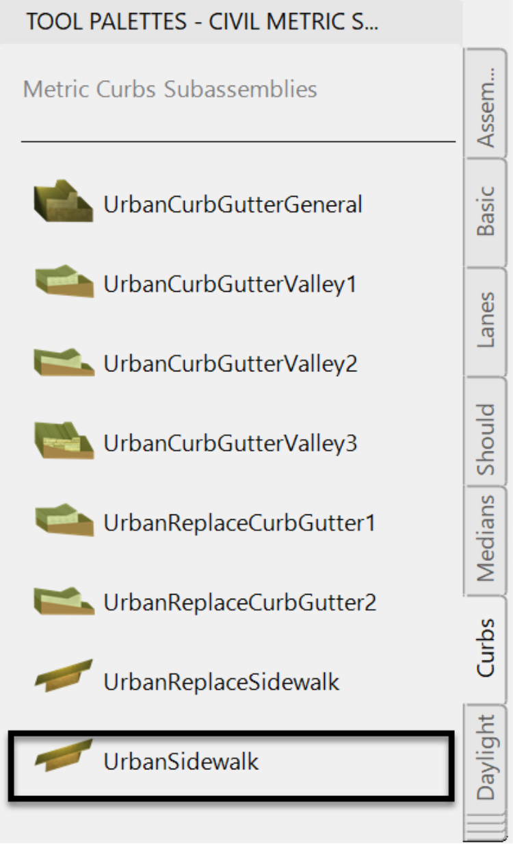
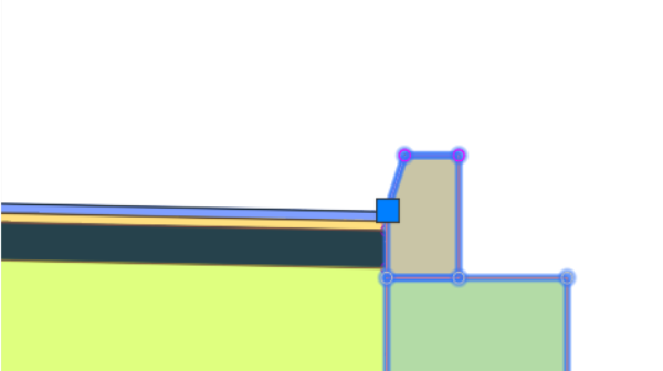
- Next, click on the back of the curb to attach the sidewalk.
- The sidewalk is then attached to the curb.
- We have now designed most of the right side of the road. We can leave it as-is and grade inside the lots later. To grade roads and street on the edges, Civil 3D offers a set of very versatile tools: Let us introduce the Generic subassemblies! These subassemblies offer different options to create links. This is helpful when we need to connect to a point that is at a specific distance, elevation or even on a given surface. A connection can also be made at a specified slope or offset. It’s easy to see situations where these subassemblies will be useful. That could be when we are daylighting to an existing ground surface or simply grading the front yard of a parcel at a given slope.
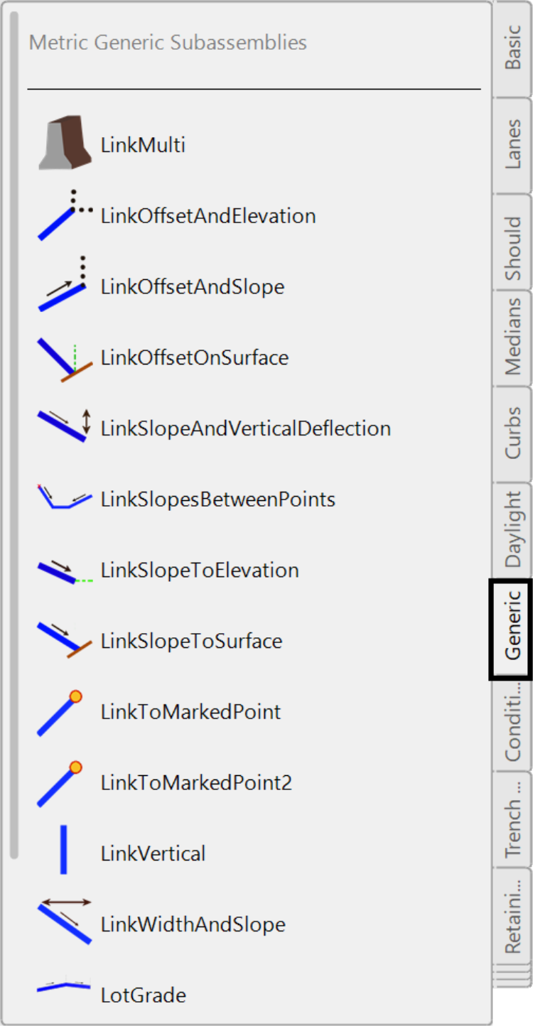
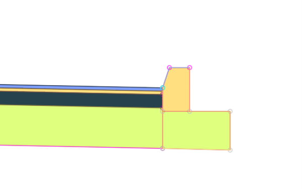
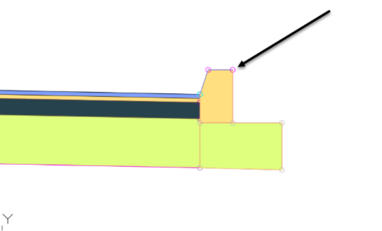
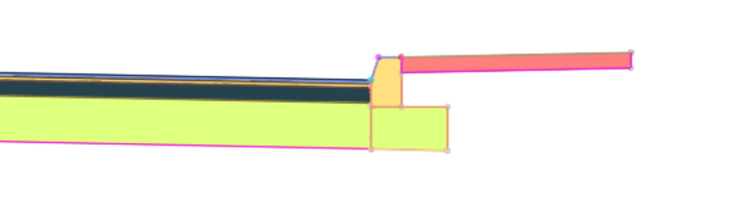
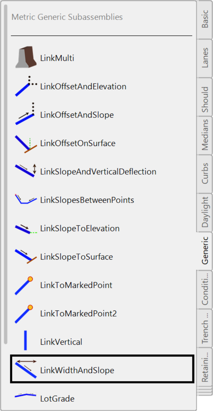
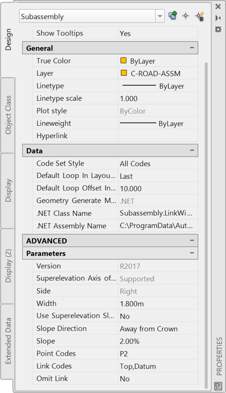
- Next, we need to create the 1.8m or 6ft landscaping strip from the end of the sidewalk to the property line. For that, we will use the LinkWidthAndSlope generic subassembly. It allows us to go from the attachment point to a specified distance, at a specific grade.
- In the property window, we need to enter the 2% slope and the 1.8m or 6ft landscaping strip.
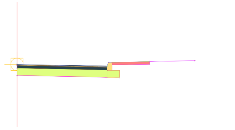
- After clicking on the top point of the sidewalk, we would have completed the right side of the road cross-section.
-
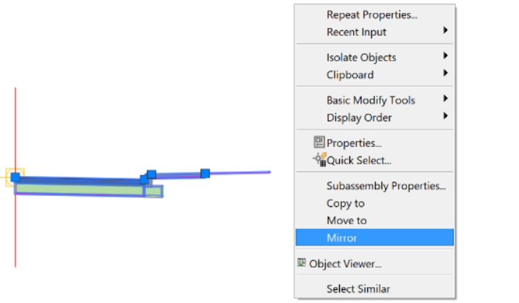
We can repeat everything we just did on the right, for the left side of the cross-section. But it would be much easier if we can simply copy what has already been done. Well, we have a command that can do just that. The mirror commandcan create a mirror image from the road center for us. Note: this is not your basic AutoCAD mirror command. To access it,
- We need to select all the subassemblies to the right. Be careful to not include the assembly baseline (vertical line) at the center, in your selection.
-
Once all assemblies to the right are selected, right-click and select a mirror.
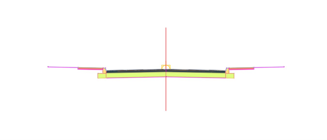
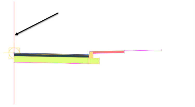
- Then, when asked to select a marker to mirror from, click on the vertical centerline.
![]()
- We have now completed the full road section. We could have graded a little further inside the property. We could use another generic subassembly, maybe the LinkSlopeToSurface one, to tie the road to the existing ground at a gentle slope. This would especially be the case if we were only building the road and develop the lots later. But, since we are also doing the lot level grading, we will leave our cross-section as-is for now and do some lot of grading later.