-
Get It
$19.99
$19.99Civil 3D Essentials Book and Practice Files
Civil 3D Cul de Sac Design: A step by step tutorial guide
Introduction to Civil 3D Cul de Sac Design
Firstly, how do we perform a Civil 3D Cul de Sac Design? Well, let's find out in this online training course. Certainly, this step by step tutorial is a part of the Civil 3D essentials book and how-to manuals.
Designing a Civil 3D cul-de-sac
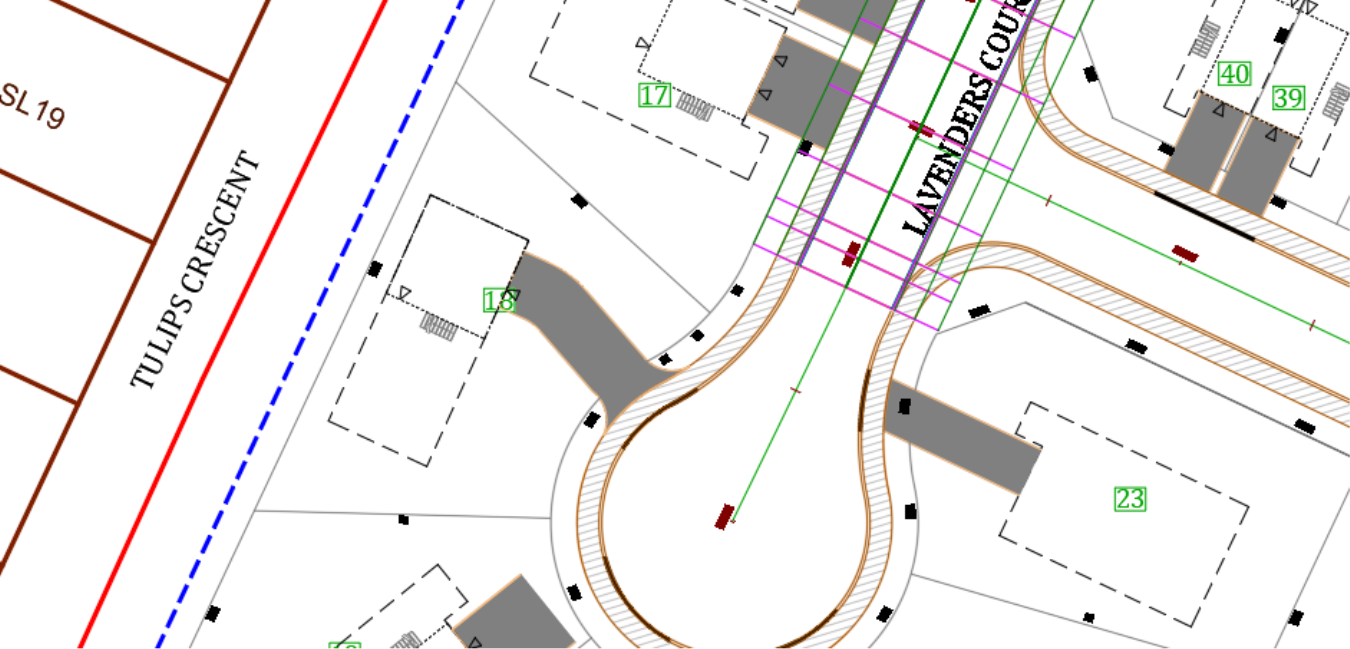
- The next step in the corridor creation process is designing the cul-de-sacs. Let’s start with the one on Lavender Court. If your corridor extends into the cul-de-sac area, simply select the zone and move it a bit north, past the start of both cul-de-sac curves. This will create some space for us to work with. Don’t worry about the exact location for now. We will tie the cul-de-sac and the tangent zones of the corridor later.For instance, the initial position may look like this.
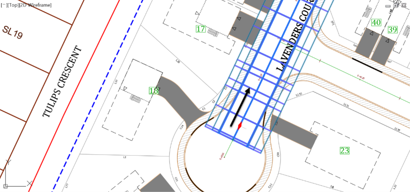
- And the final position, after dragging will look like this.
- The bad news is that we don’t have an automatic tool like the intersection wizard to create cul-de-sacs. But the good news is that with a little bit of creativity, we can create cul-de-sacs as easily as intersections, if not easier. Besides, if we master this process, we will be able to create corridors in many other circumstances.
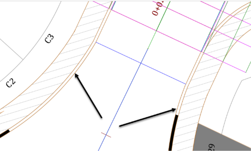
- The idea here is to consider the cul-de-sac as a curb return as we did for the intersection. That means, instead of working from the centerline outward to the curb, we need to work from the curb inward to the road centerline. So, we must have an alignment and profile for the curb line and apply the curb return subassembly to create a corridor.
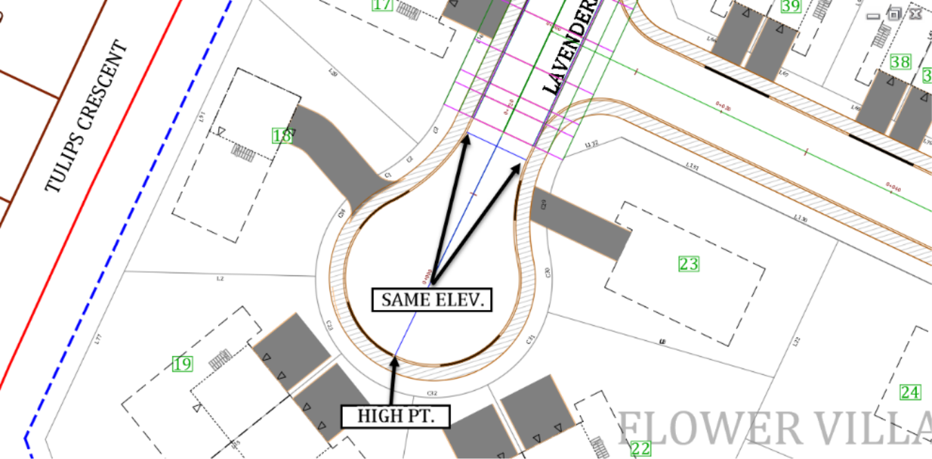
- When creating the curb profile, we want to have the same elevations at the start and end of the zone and set a high point at the end of the cul-de-sac.
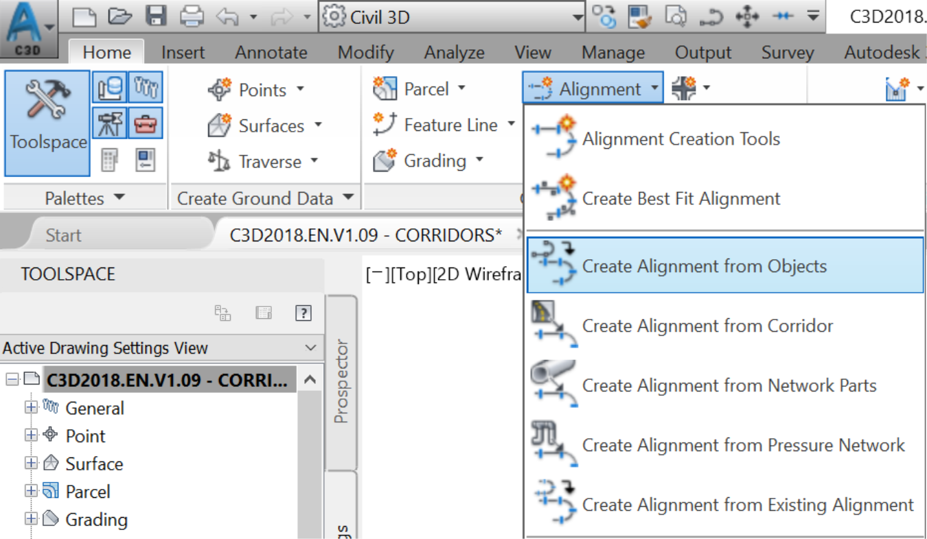
- Now, let’s start creating the curb profile. First, from the ribbon, use the Create Alignment from Objects command.
- Select the curb line.
- At the command line, press Enter twice, first to confirm the polyline, then a second time to accept the direction of the alignment.
- In the Create Alignment from Objects window, assign the name, description and alignment style which we will set to Curb. To avoid cluttering the drawing, we will not assign any label. For Conversion Options, we do not want to Add curves between tangents nor do we want to Erase the existing entity.
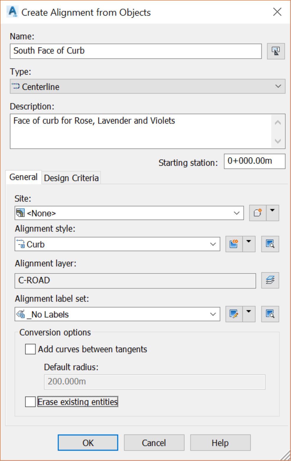
- Click OK to create the alignment.
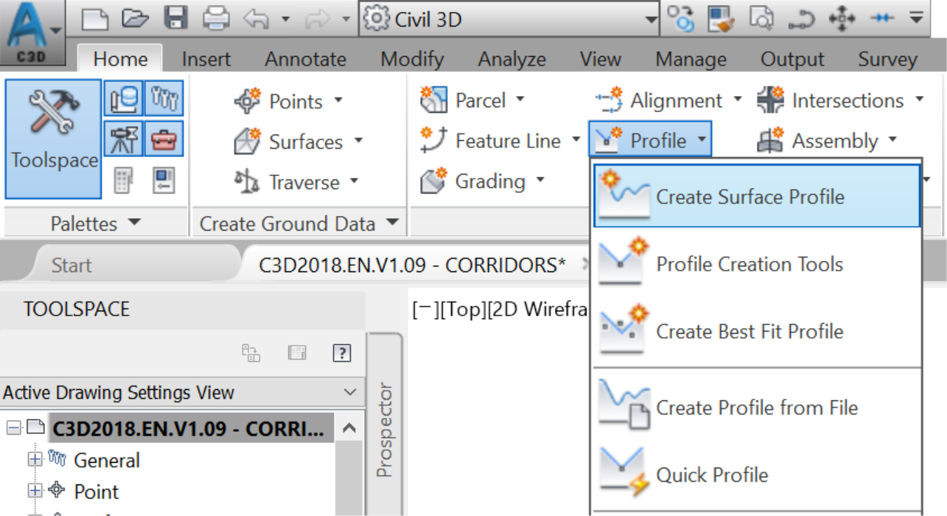
- Next, we need to associate a profile to the alignment. Create a profile using the corridor surface, from the Create Surface Profile command on the ribbon.
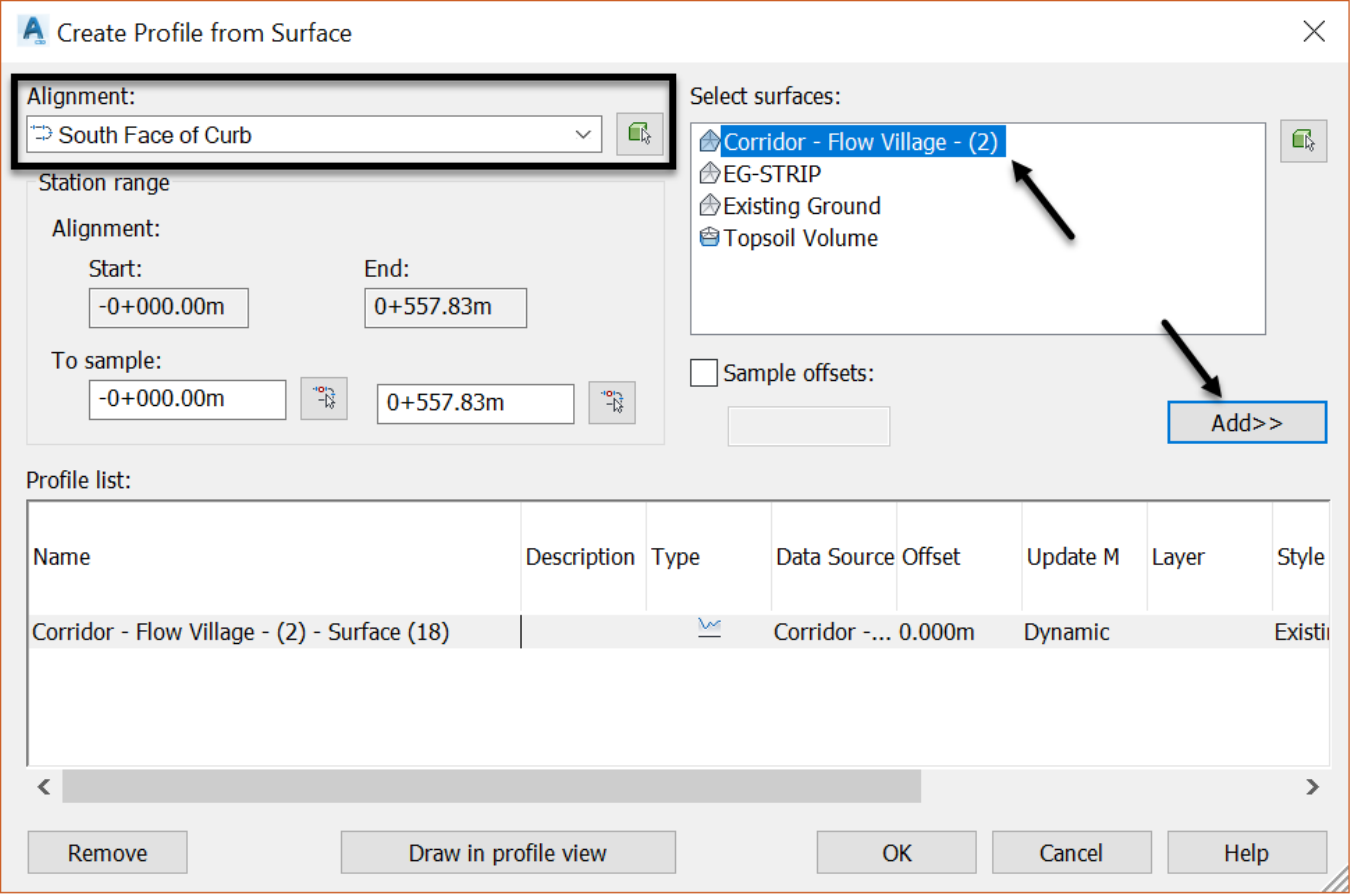
- After you’ve added the Flower Village Corridor surface using the Add button, click on Draw in profile view. We will accept the default settings for the profile creation because we have already used them and can change them if we need to.
- Next, click somewhere in the drawing area, under the existing profile views, to specify the bottom left corner of the profile view.
- This profile represents the entire length of the curb. We need to identify where our cul-de-sac is located, in the profile view. We have multiple options to do that. One of the options is to: create points at the start and end of the cul-de-sac, then project them to the profile view.
-
Using the manual point creation command create points at the two locations mentioned. Let’s give them the descriptions DG-CDS1, DG-CDS2, just to indicate that they are design points for the Cul-De-Sac.
-
Using the manual point creation command create points at the two locations mentioned. Let’s give them the descriptions DG-CDS1, DG-CDS2, just to indicate that they are design points for the Cul-De-Sac.
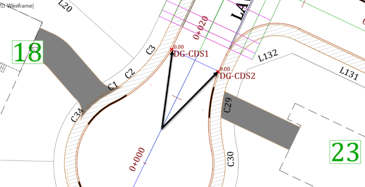
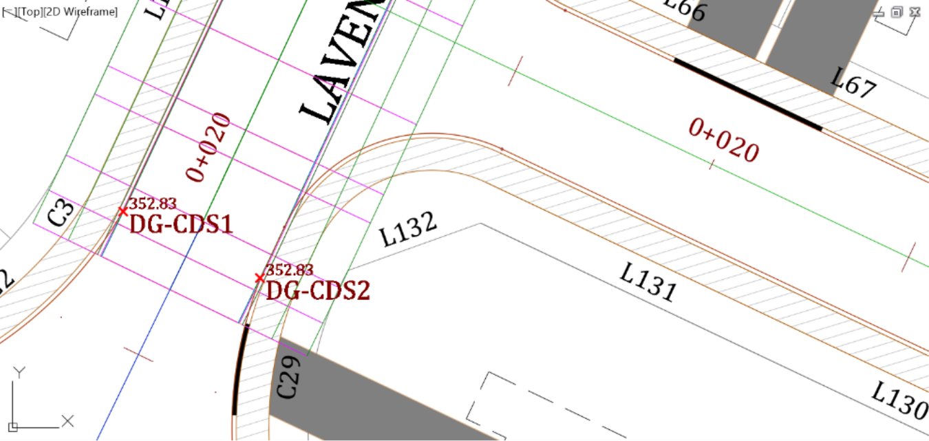
- Next, we need to assign the point elevations. We want DG-CDS1 and DG-CDS2 to have the same elevations as the existing corridor.
- To do that, first, temporarily drag the corridor south, to cover the points area.
-
Also, make sure the corridor surface is updated. In the prospector, select the Corridor – Flower Village's surface, right-click and rebuild the surface.
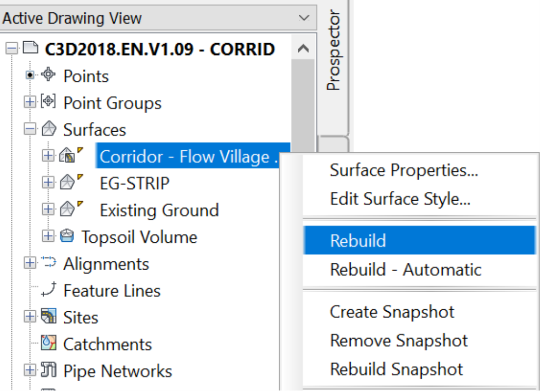
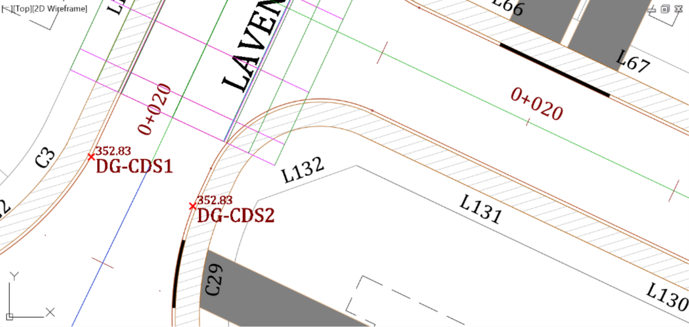
- Once the corridor is dragged south, zoom to the 2 points and make sure they are on the pavement, not on the curb. If you need to, move them slightly to the pavement area.
- Next, select the two points and elevate them to the corridor surface, using the Elevations from Surface command.
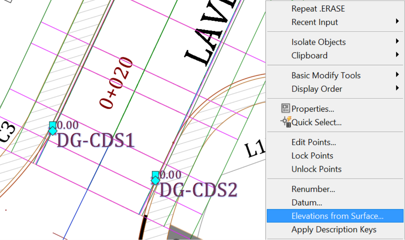
- In the Select surface window, select Corridor – Flower Village and click OK. The points are now assigned to the corridor elevations.
- Now, we can move the corridor back, as it has served its temporary purpose of providing the needed elevations.
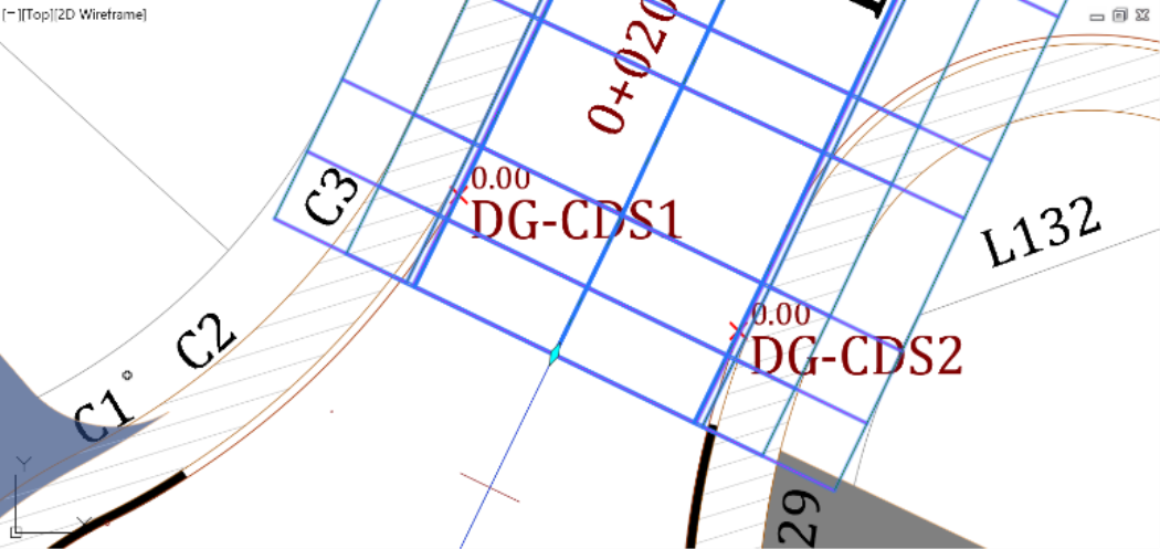
- Next, we will use the two points to create a profile for the curb return. The points will also help us locate the cul-de-sac area on the profile view.
- Now, zoom to the curb profile view.
- Then, Select it and on the ribbon, run the command Project Objects To Profile View.
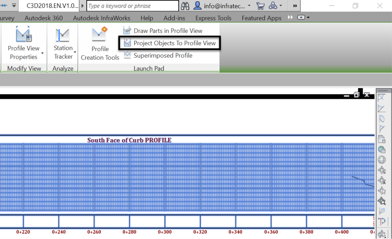
- In the drawing, select the two points and press enter at the command line to project them to the curb profile view.
- In the next window, we can change the projected object styles, label styles, and elevation options. We will leave them as-is, for now, since we want to use the original elevations obtained from the corridor.
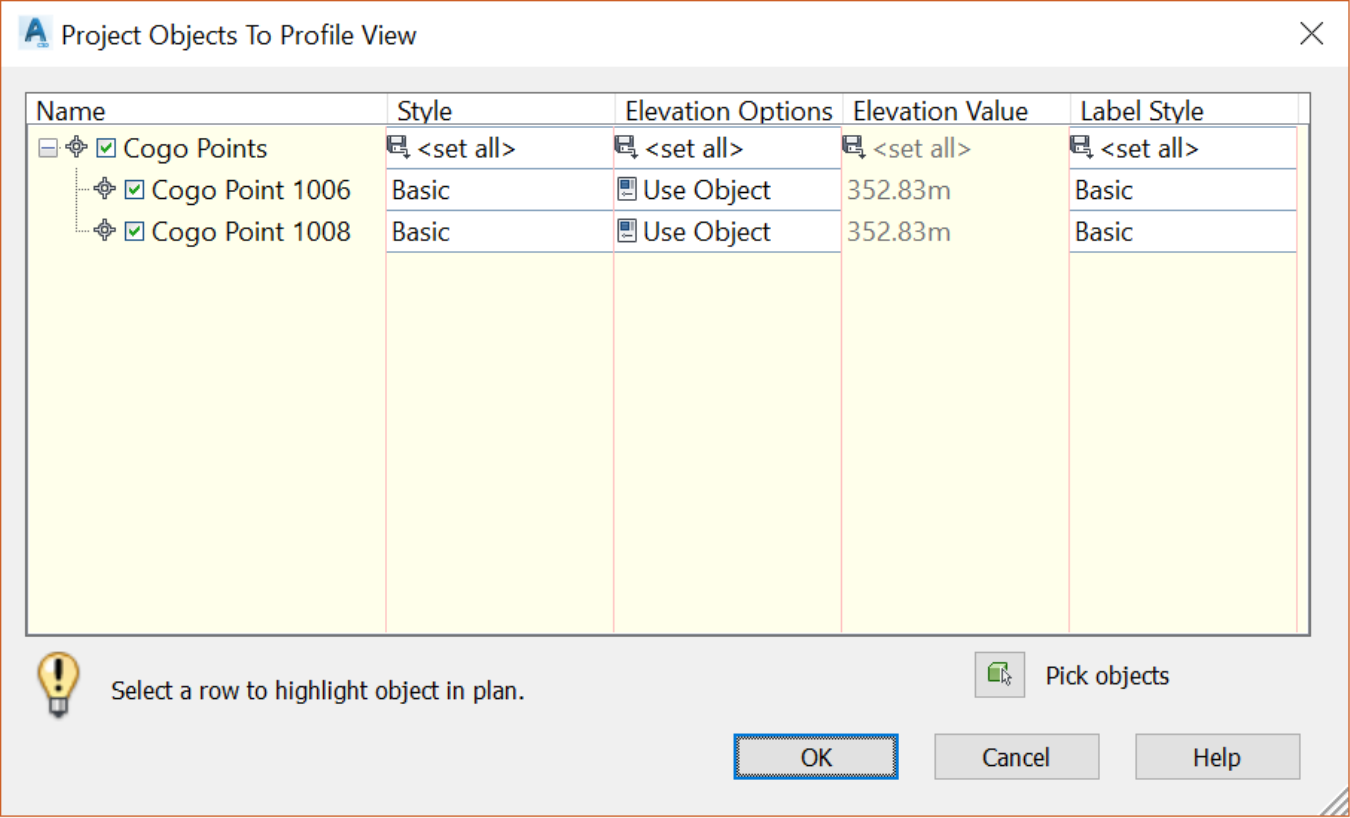
- Click OK to close the project window. Once you zoom back to the profile view, you will notice the projected points. This gives us a clue about the location of the cul-de-sac on the alignment.
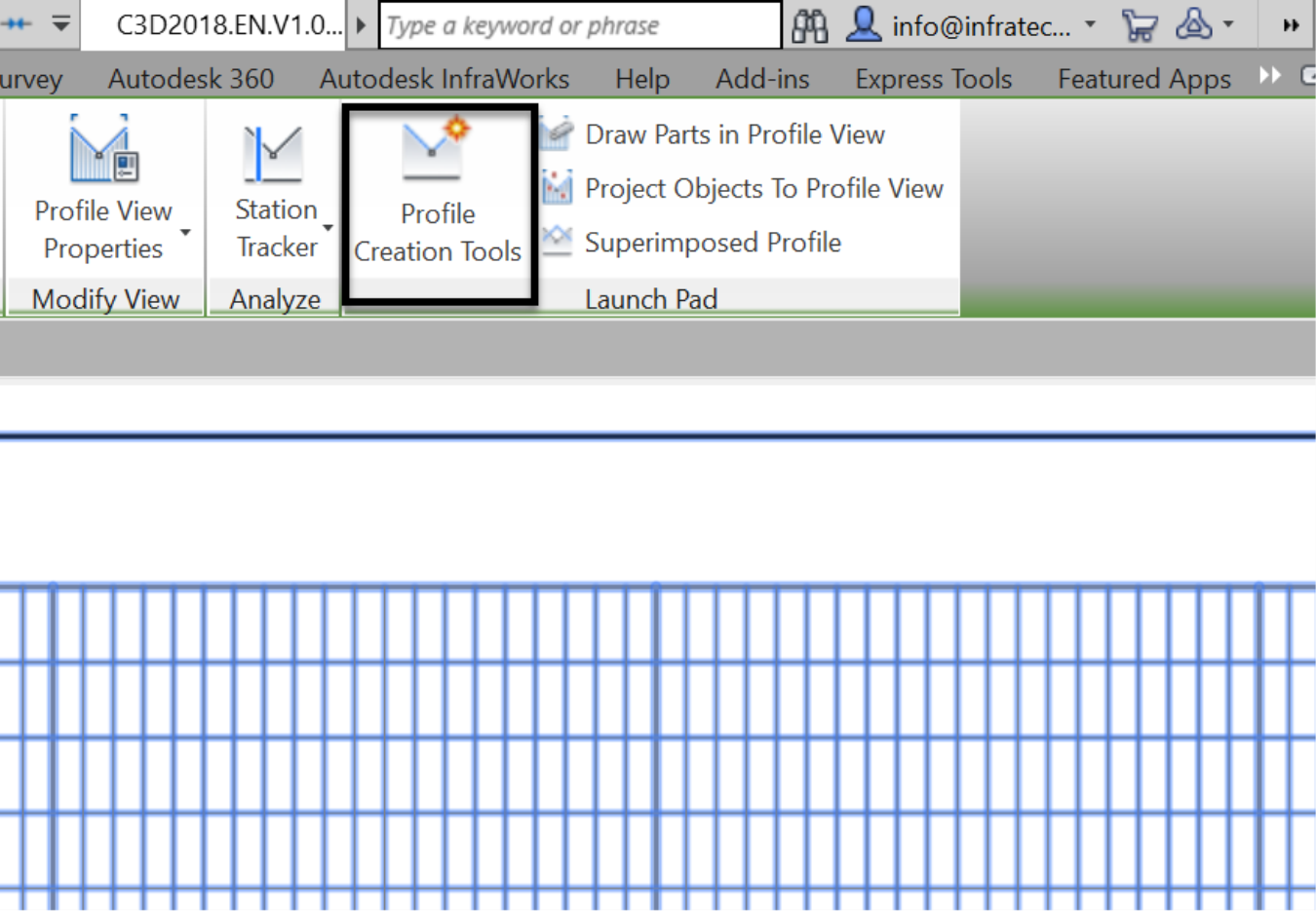
- We can easily create the profile now. Select the profile view and run the Profile Creation Tools command from the ribbon.
- In the new window, assign the name to the profile, give it a description and choose a label set. This will not be a profile that we will print, so we don’t need to worry about appearance here.
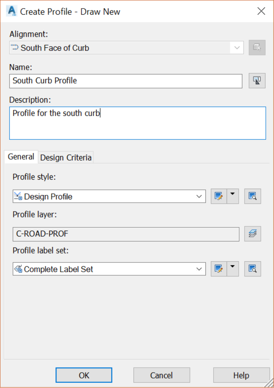
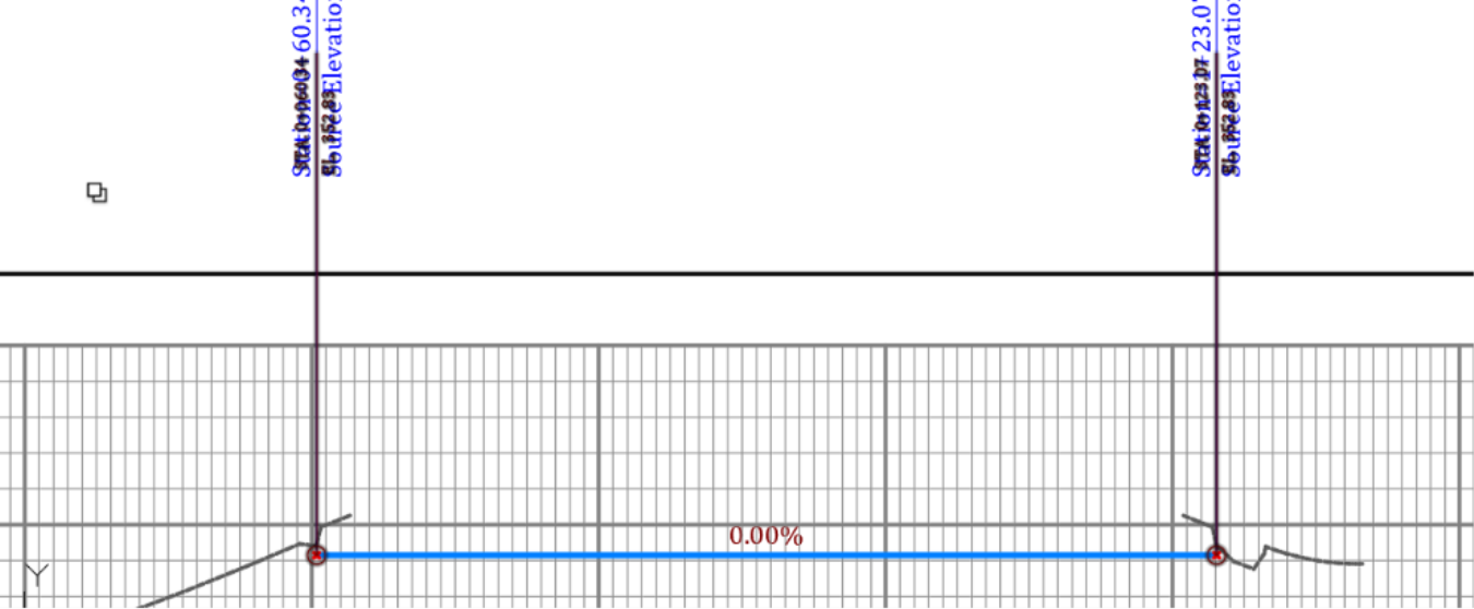
- Click OK. In the Profile Layout Tools, draw a tangent between the two projected points. You may need to use the node object snap mode to draw with precision.
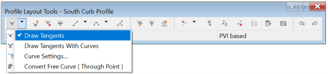
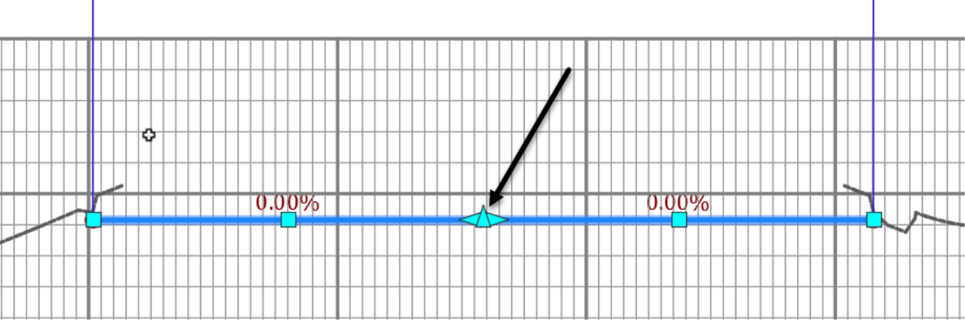
- Next, we need to create the high point of the cul-de-sac. Use the Profile Layout Tools to create a PVI (Point of Vertical Intersection) in the middle of the tangent.
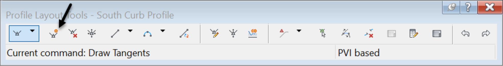
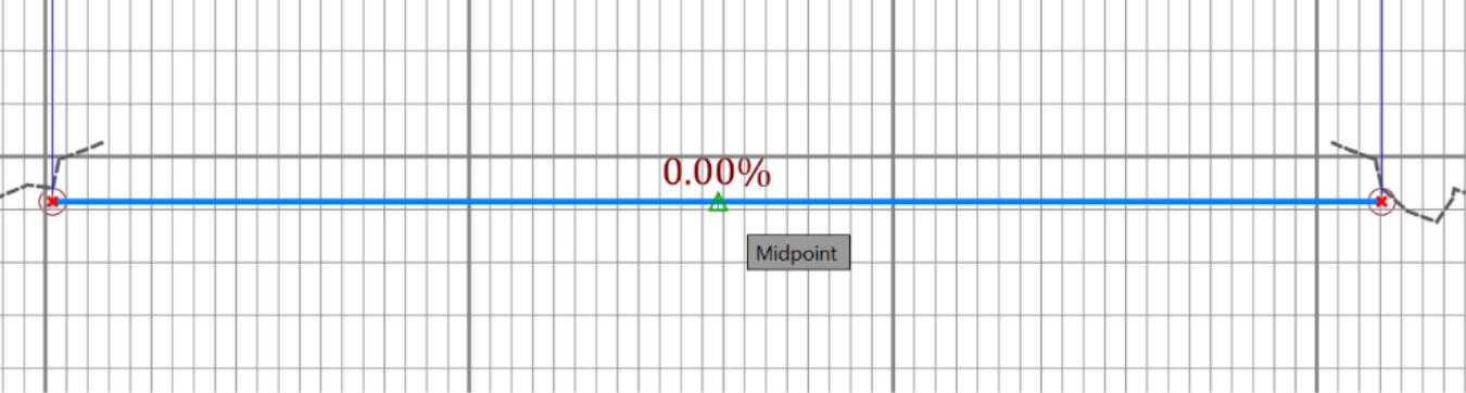
- Next, with your middle object snap activated, click on the middle of the profile tangent, around the 0.00% slope label, to create the PVI for the high point.
- All that is left for the profile creation is to set the slopes. You can do it manually by grabbing the PVI point and slide it up, with your Ortho mode activated.
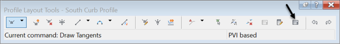
- Or, you can set it with precision by using the tabular editing option of profiles. To do that, click on the Grid View command of the layout tools.
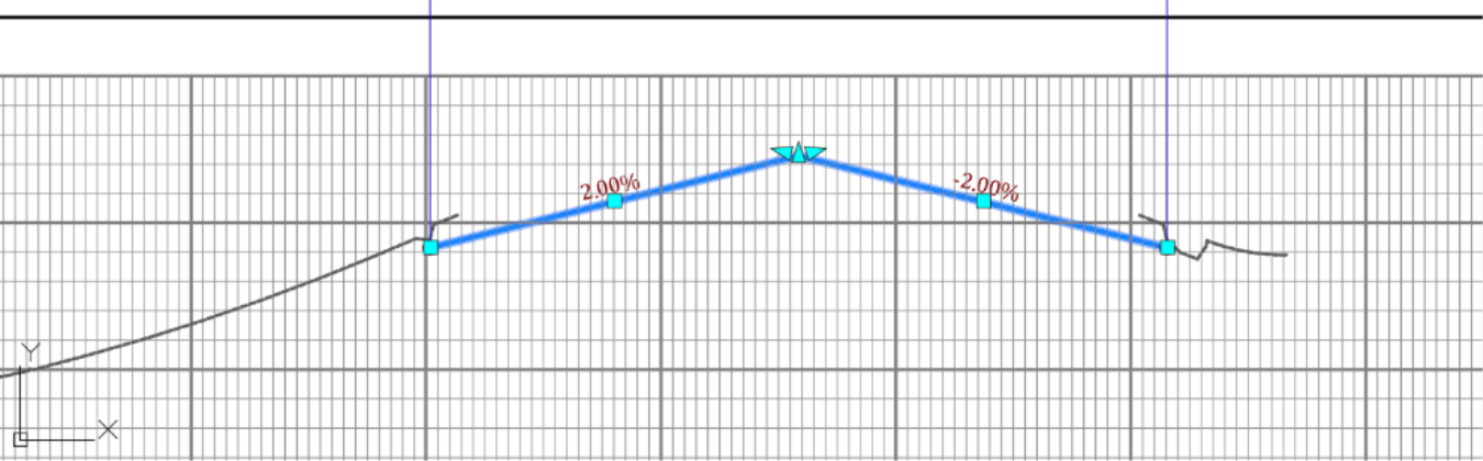
- In the Panorama, set the grade out to 2%.
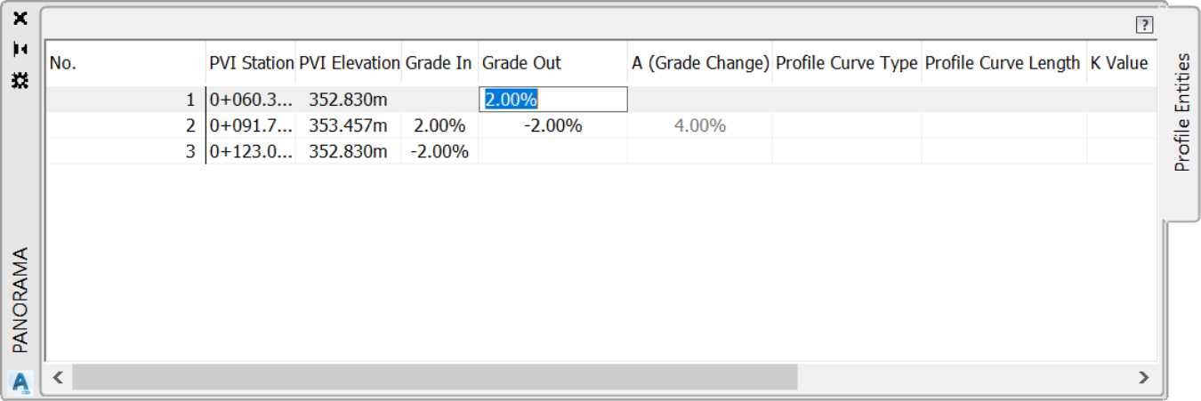
- That adjusts the profile automatically and creates a high point, with a 2% grade.
- Now, we have an alignment, a profile, and subassembly. We are thus ready to create a new corridor for the cul-de-sac. Or, we can add a new baseline, to the existing corridor, to represent the cul-de-sac.
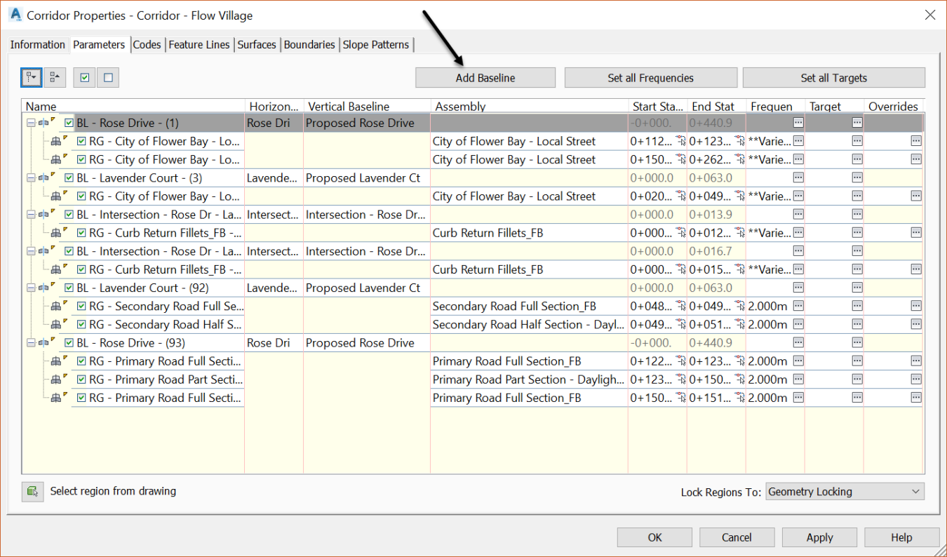
- Let’s go with the latter option. Select the corridor. Right-click, then select Corridor Properties and click on the Parameters tab.
- Next, click on Add Baseline.
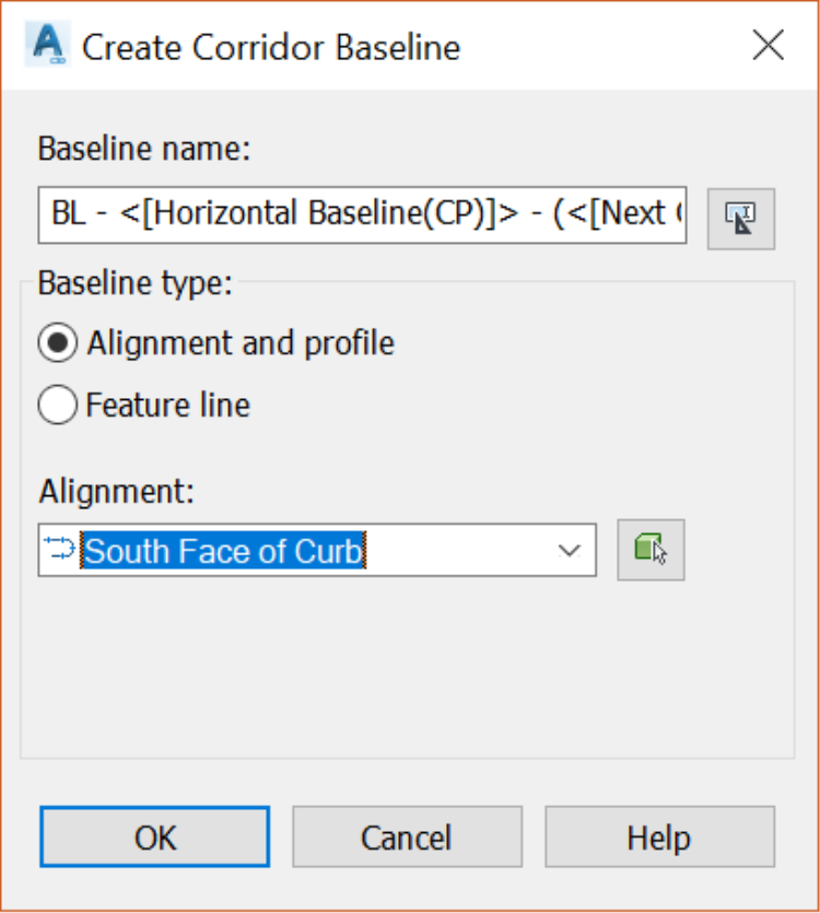
- Select the face of curb alignment and click OK
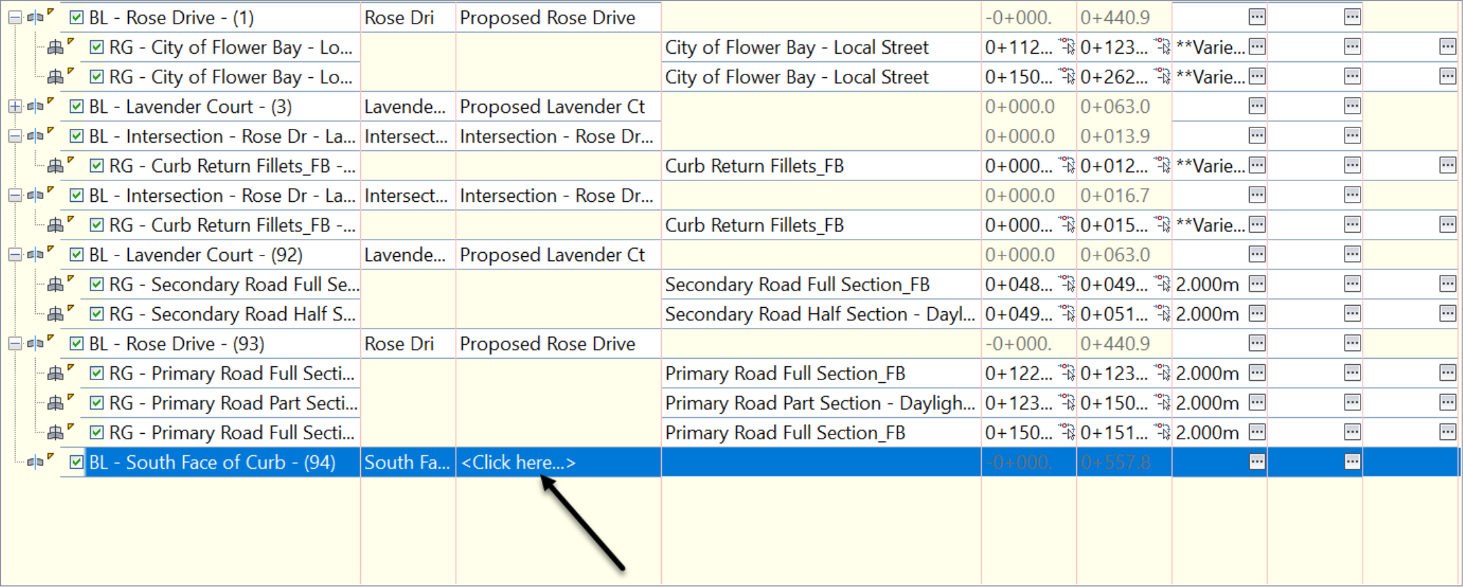
- Then, click to specify the profile to use for the baseline.
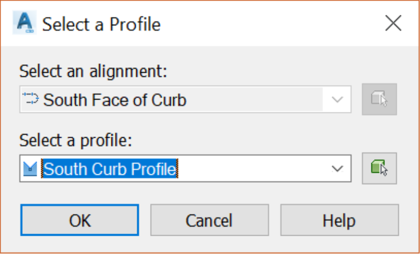
- In the profile selection window, choose the curb profile we have just created and click OK
- Now, we need to specify, along the baseline, where to add the cul-de-sac portion of the corridor. This is done by creating a Region and specifying a start and end station for the Region. Select the new baseline, right-click and select Add Region.
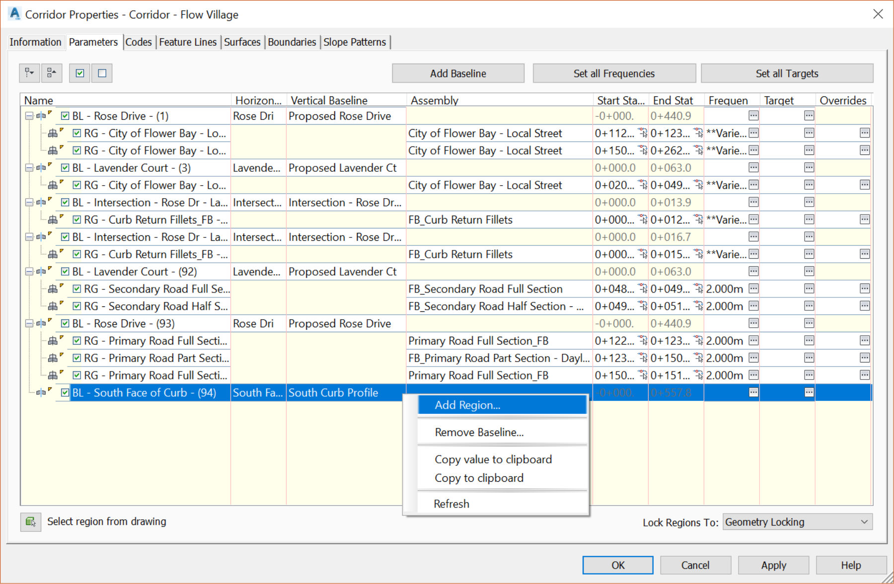
- In the Create Corridor Region window, keep the default Region name. Then, select Curb Return Fillets -FBassembly, and click OK to close the window.
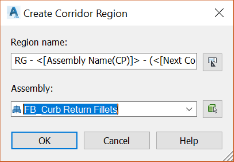
- The new region is added. By default, it stretches the entire length of the baseline, which is not representative of what we are trying to do. So, we need to specify a start and end station.
- Click on the “+” sign to the left of the baseline name,
- then click on the small arrow icon to the right of the start station.
-
This will take you to the drawing area to click on the point you would like to use as a start point. Of course, in this case, it is going to be DG-CDS1. You may need to have the Node mode object snap activated.
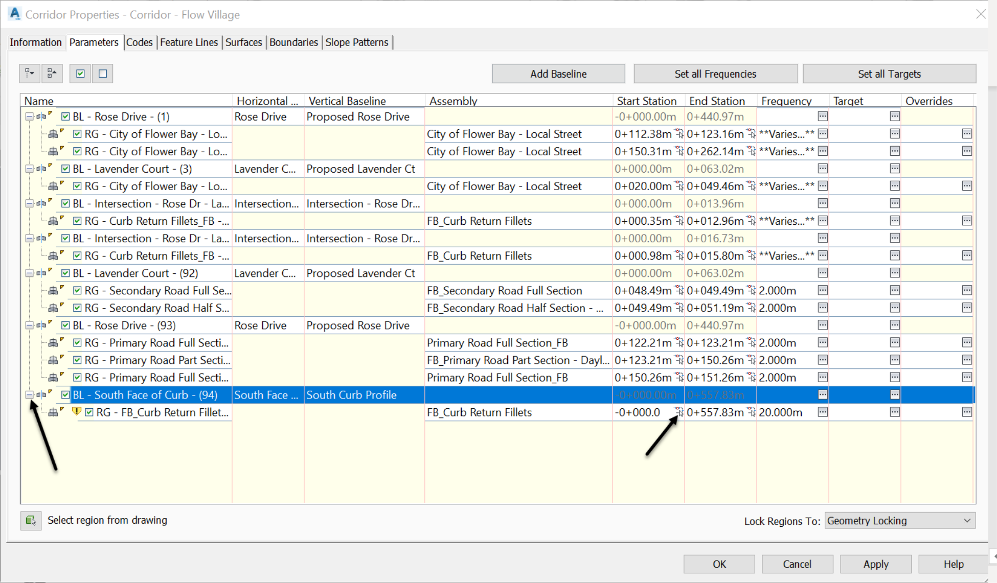
- Once in the drawing, click on DG-CDS1. This will automatically pick up the corresponding station.
- Repeat the previous steps for the End Station and this time click on DG-CDS2.
- We have now both the start and end station specified, along with a profile and an assembly. This should give us everything we need to create a corridor region. So, let’s click OK to close this window and check it out.
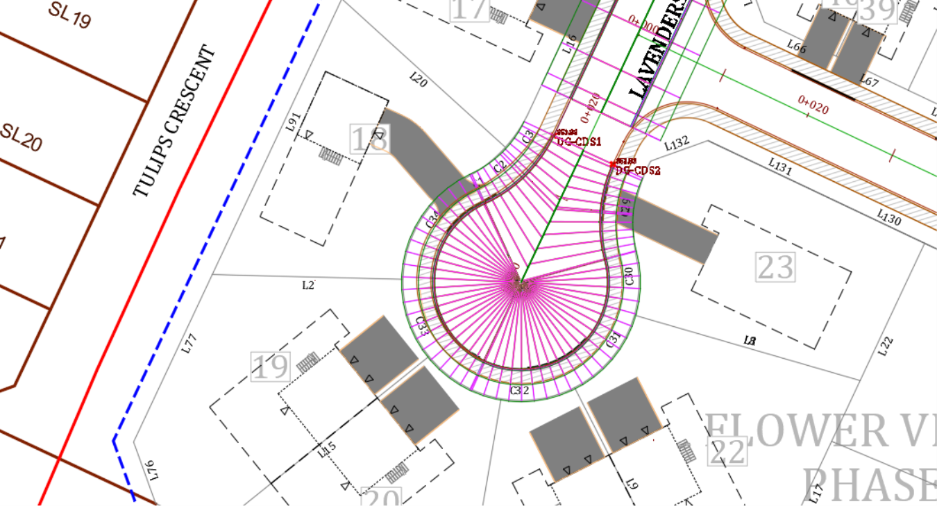
- Now, it looks like we have created a cul-de-sac.
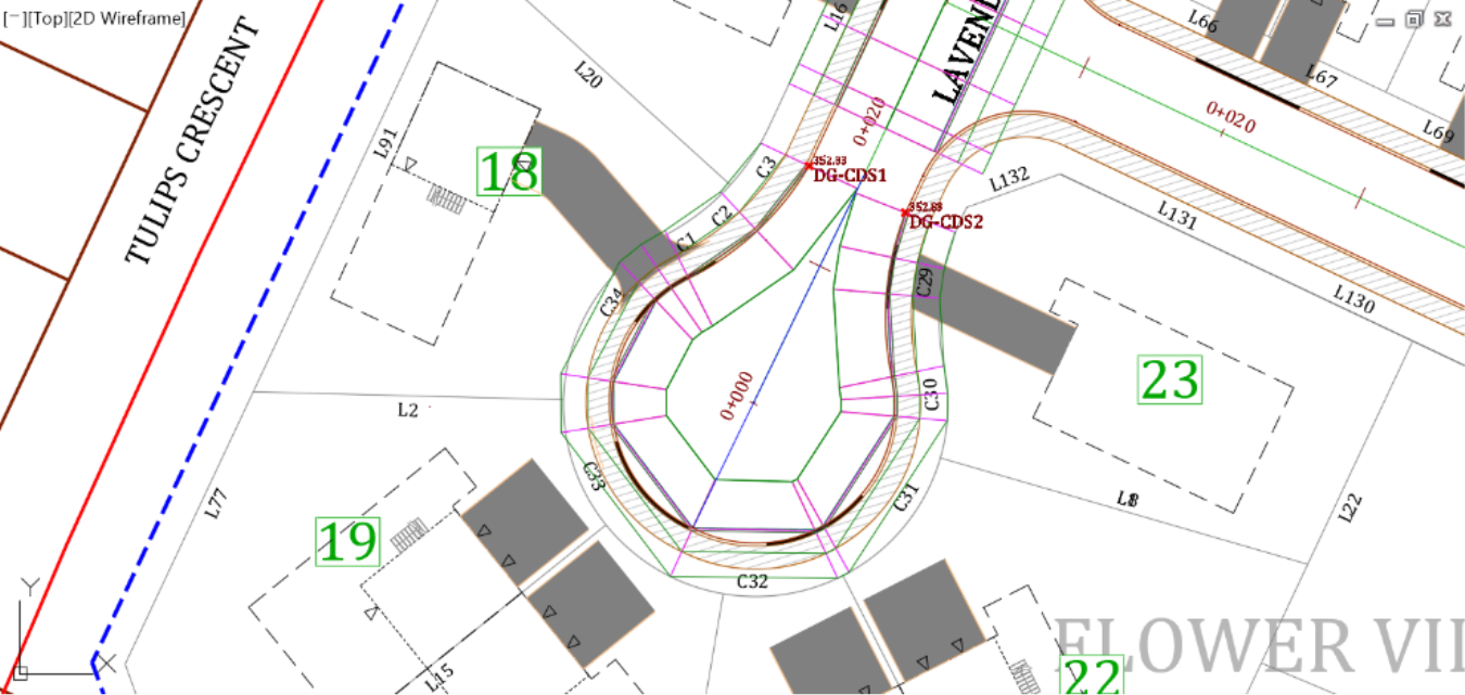
- However, it just looks like we can do better than this. The cul-de-sac bulb is not filled, and the lines look like something is off. Well, that’s because we have not inserted enough cross-sections and haven’t set a target to fill out the void in the middle.
- First, let’s insert more sections. This is accomplished by using tighter frequencies. Select the corridor, on the ribbon, and run the Edit Frequency command.
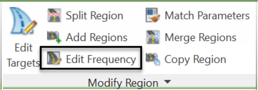
- When prompted at the command line to specify a region to edit, click inside the corridor, around the cul-de-sac area.
![]()
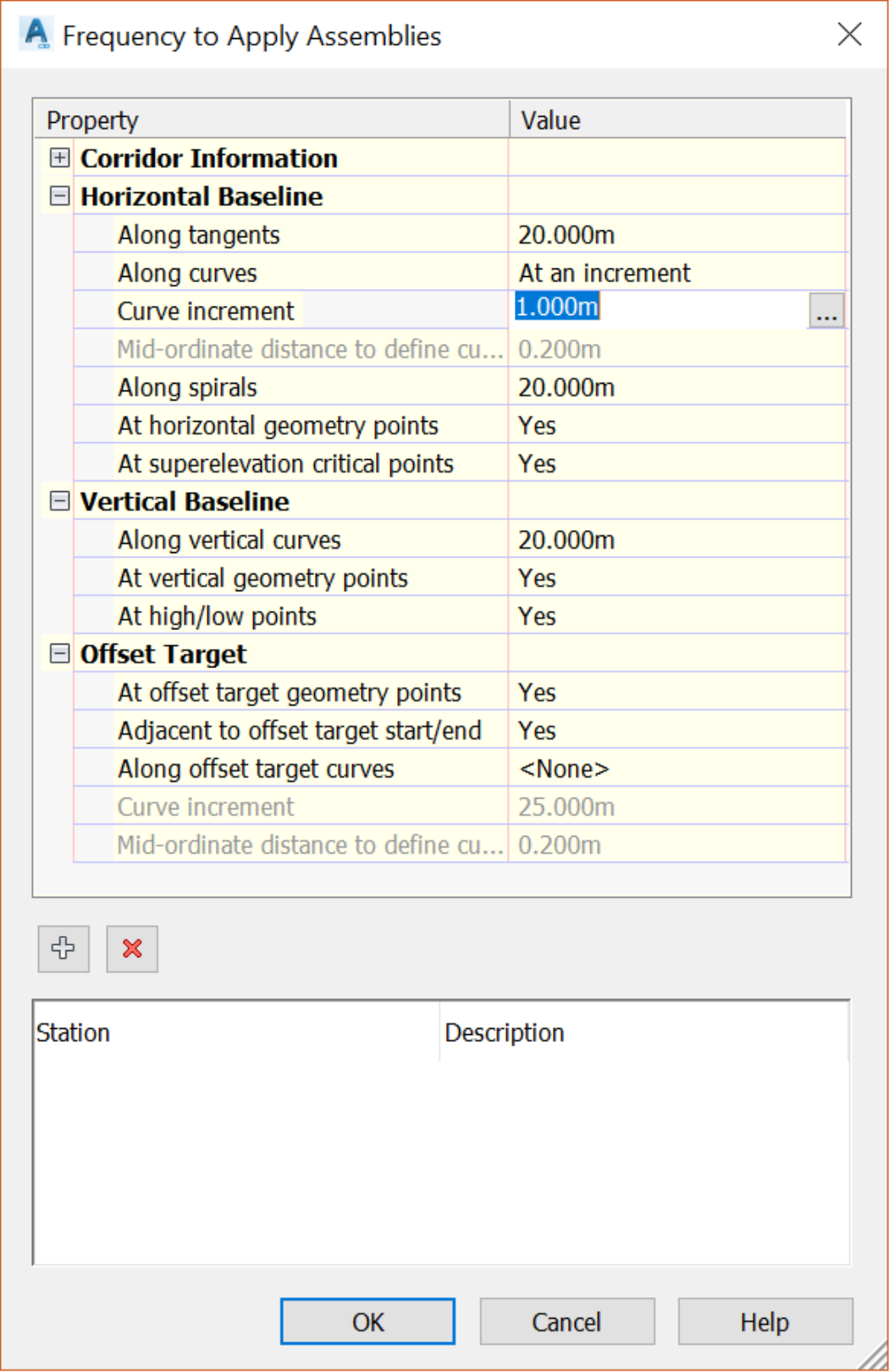
- In the next window, set the curve increment to 0.5m or 2ft. We only have to worry about the curves, since there is no tangent in the cul-de-sac region.
- Click OK to exit the frequency window.
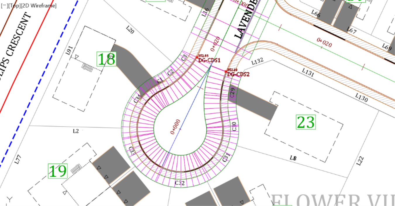
- Applying a tighter frequency makes the corridor look much smoother.
- Now, unless we are required to create an island in the center of the cul-de-sac, we must pave the void in the middle. To do that, we need to use targets and extend the asphalt to the center of the pavement. Select the corridor, on the ribbon run the Edit Targets commands.
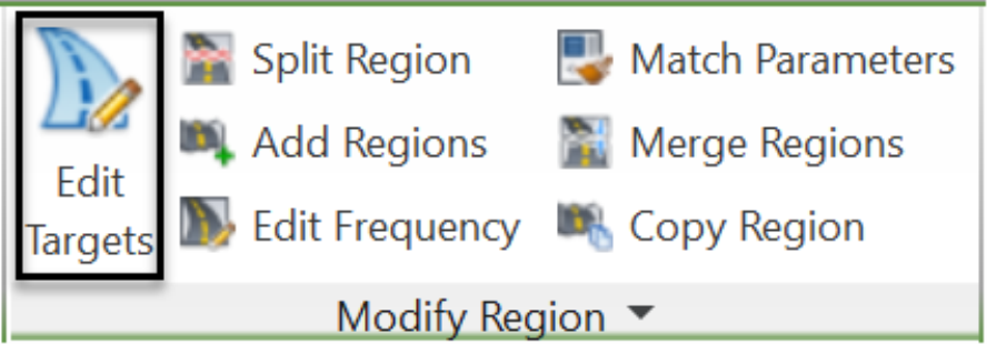
- When prompted at the command line to specify a region to edit, click inside the corridor, around the cul-de-sac area.
![]()
- As we’ve seen before, we can assign three types of targets to a corridor: a surface, an offset or width, and a slope or elevation. To extend the cul-de-sac pavement, we need to use the width and elevation target types to extend to the centerline alignment and profile. So, in the new window, on the Width Target line, in the Object Name column, click on <None> to specify the width to target.
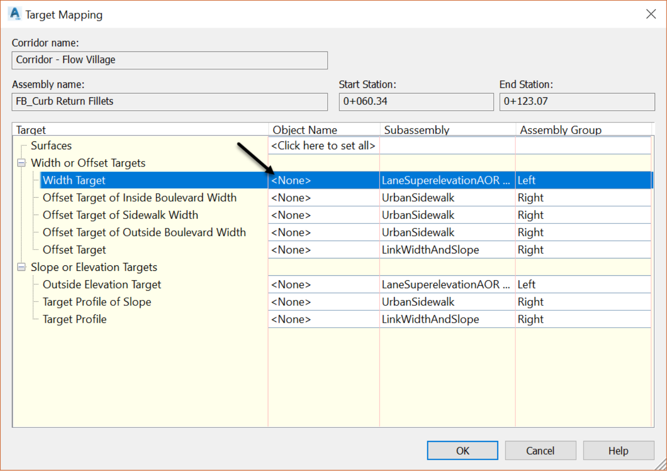
- Then in the Set Width or Offset Target window, specify the alignment to target. In here, we can target alignments or other objects such as polylines or feature lines. In this case, choose the Lavender Court alignment.
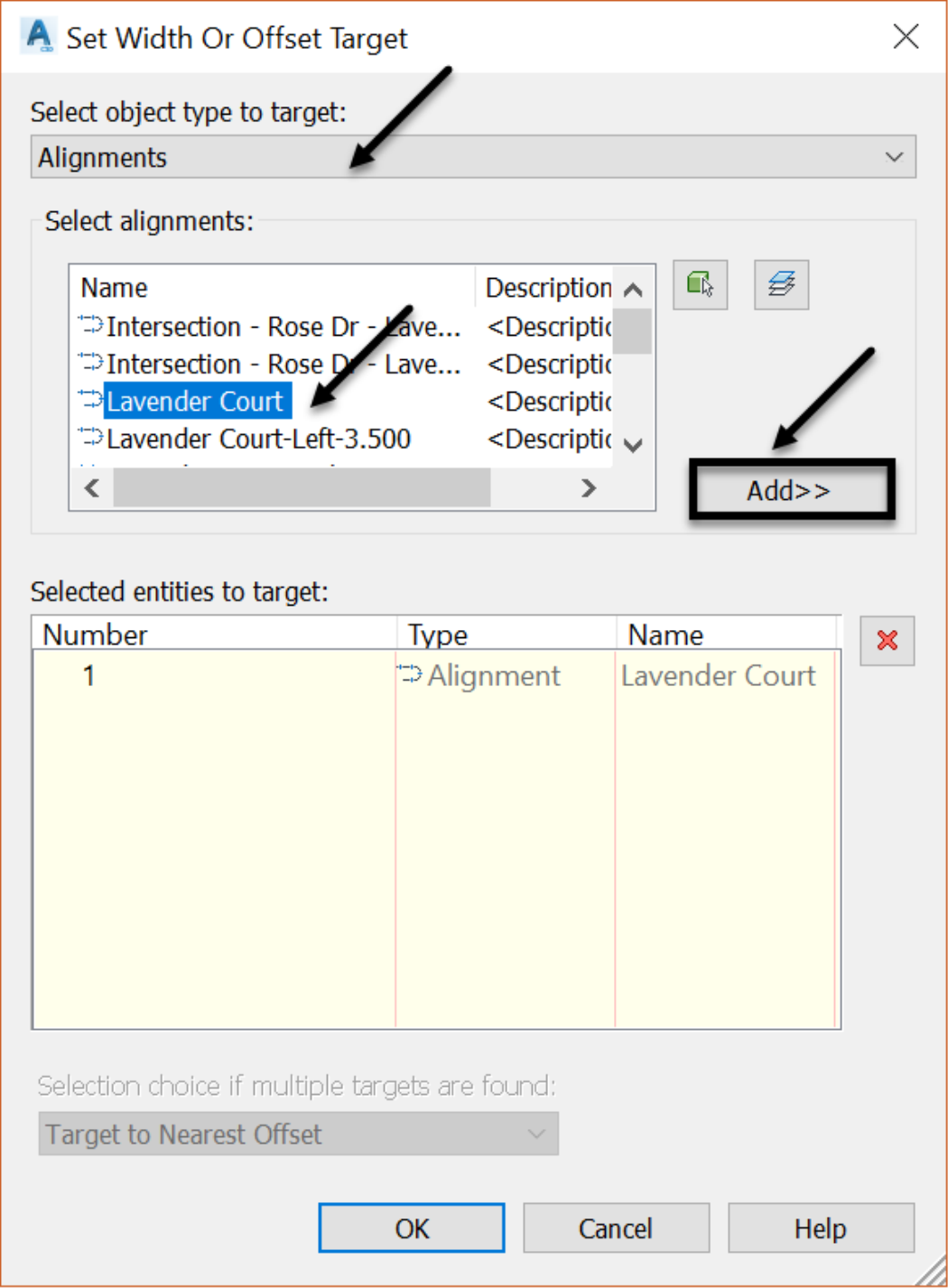
- Click OK twice to preview the changes made by targeting the center line.
- Next, we can add the Lavender Court road centerline profile as a second target. But, if the cul-de-sac is perfectly symmetrical, there will be no need to do that. The uniform 2% slope will be carried throughout the cul-de-sac, from the edge of pavement to the centerline.