-
Get It
$19.99
$19.99Civil 3D Essentials Book and Practice Files
Civil 3D intersection: A step by step tutorial guide
Introduction to Civil 3D intersection
Firstly, what is a Civil 3D intersection? Well, let's find out in this online training course.
Now, we need to create the intersection to fill the void we created by splitting the corridor and moving the regions. An intersection can be created automatically or manually by using assemblies and targets. Let's use the automatic method.
On the ribbon, run the Create intersection command.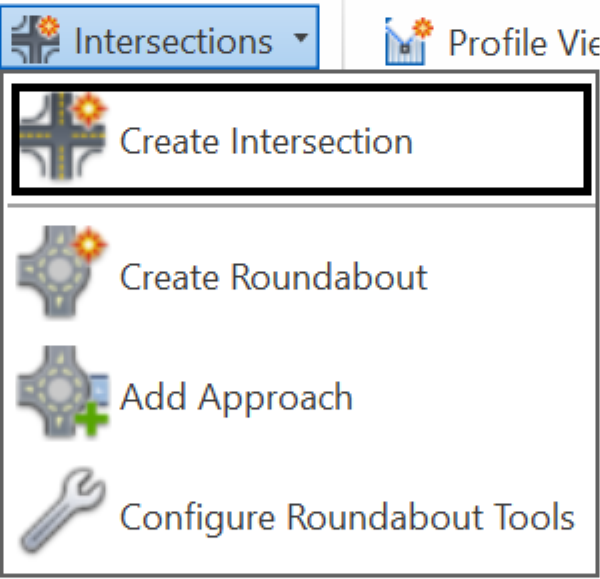
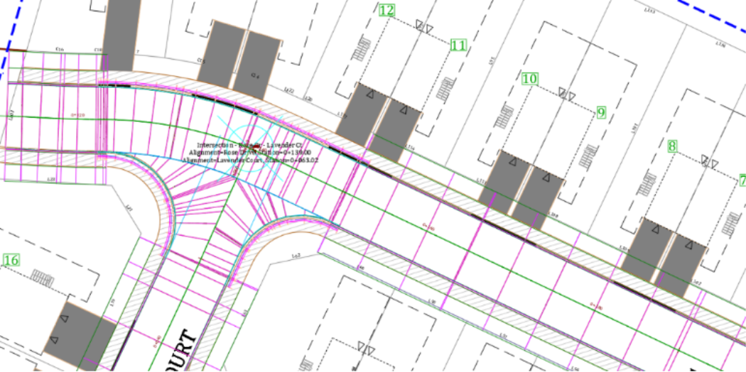
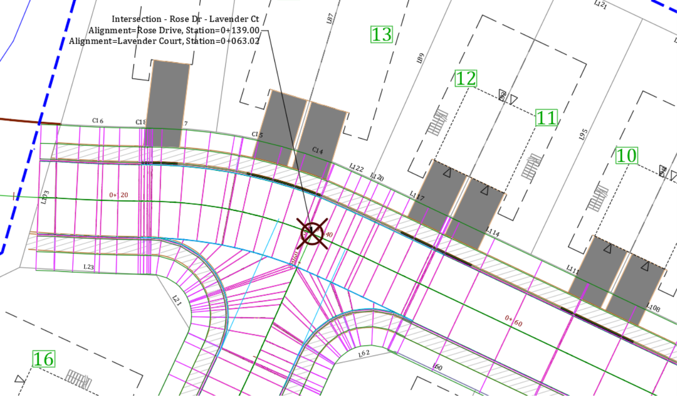
Select the point by clicking on the intersection of Rose Drive and Lavender Court.
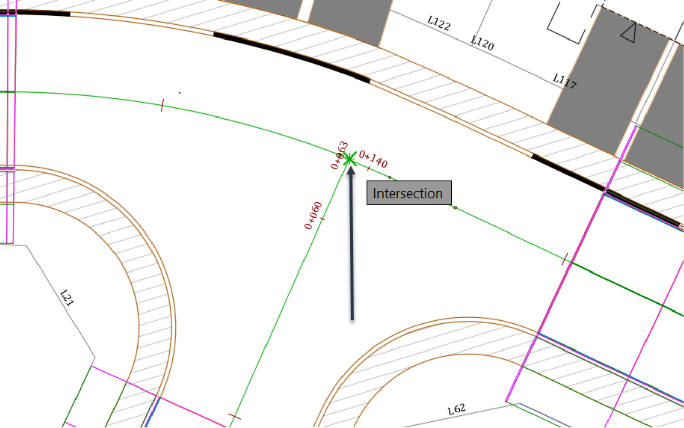
That opens the Create Intersection wizard. When you use two crossing alignments, you should specify the principal road and the secondary one. For a “T” type intersection, the continuous street (Rose Drive) will automatically be designated as the principal road. The discontinued street (Lavender Court) will be the secondary road.
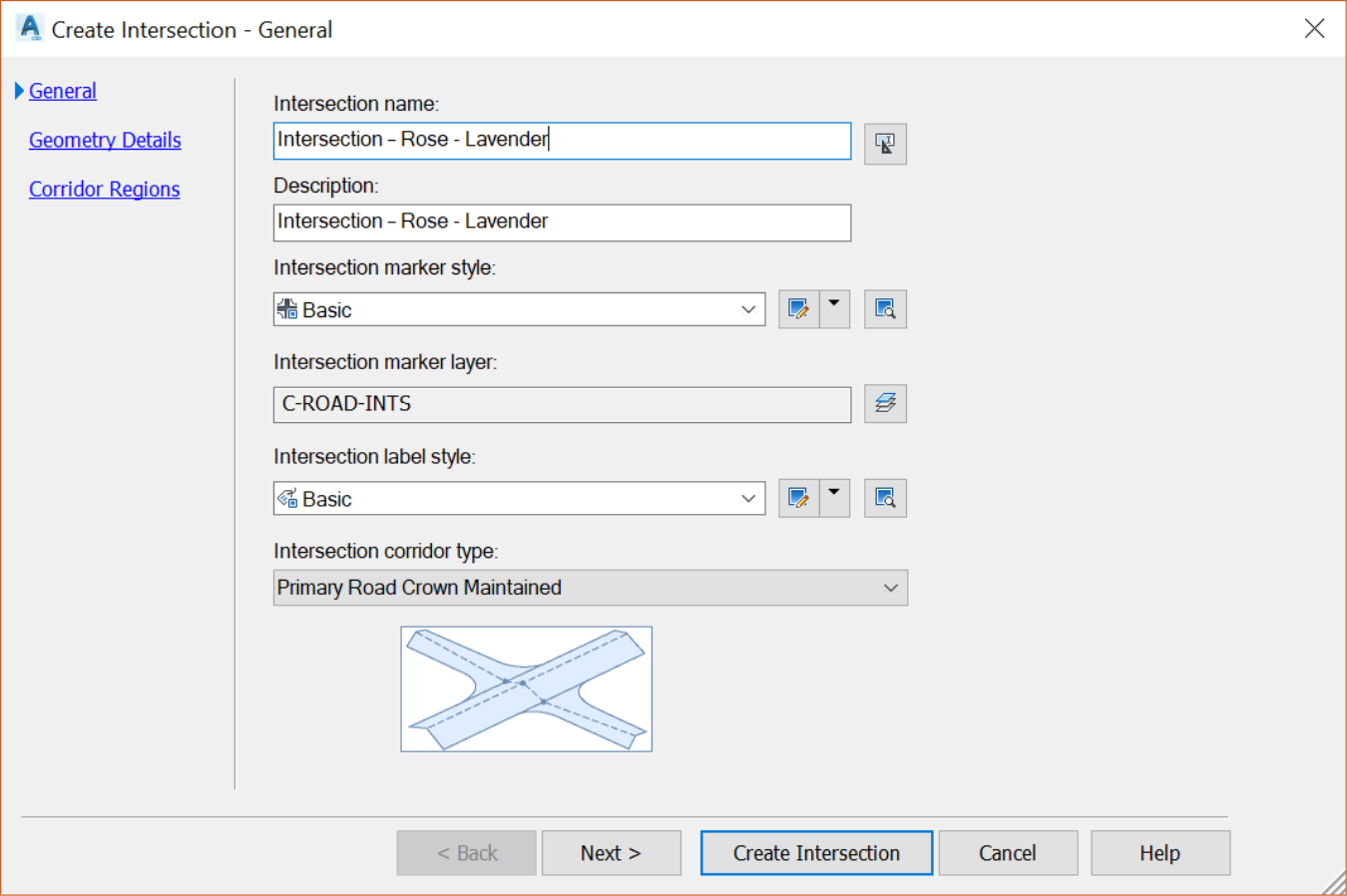
On the General page, we can specify general details for the intersection object, such as name, styles and corridor type.
- Let’s name it Intersection – Rose - Lavender.
- For description we will use the same as the name, meaning Intersection – Rose – Lavender.
- For the styles and layer, leave the default values.
- Finally, for corridor type choose Primary Road Crown Maintained. With this option, the crown of the primary road is maintained, while the secondary road is adjusted to match the primary road at the edges.
Click Next to move to the Geometry Details page. It is on this page that we specify most of the design parameters.
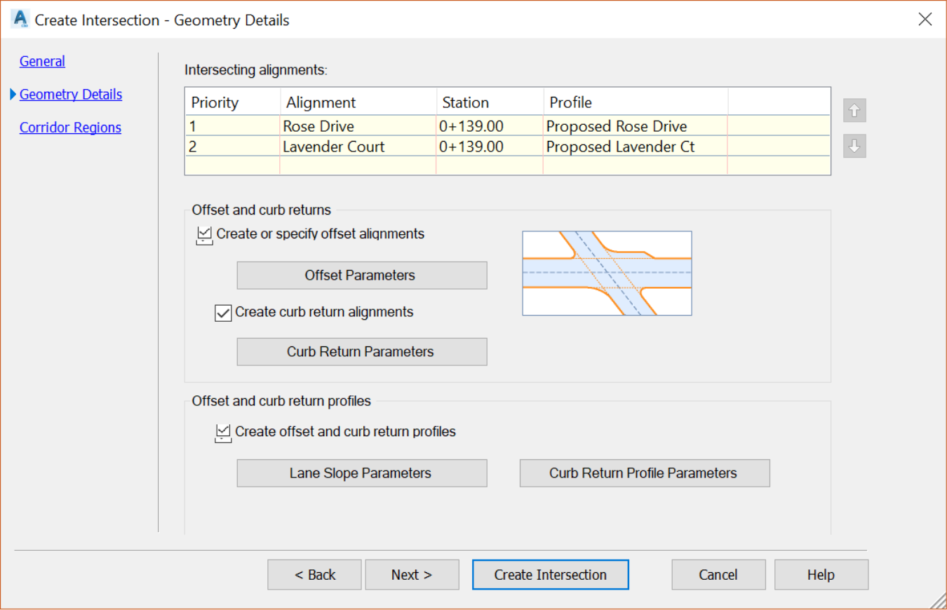
The first type of parameters we need to adjust is the street widths.
- Click on Offset parameters.
Change the offset value for each of the four street lanes to 3.5m or 11ft. Notice how the image at the bottom adjusts to give us some visual cues on which element of the intersection is being adjusted.
Then, click OK to close the Offset Parameters window.
Next, we need to adjust the curb returns on the Geometry Details page.
- Click on Curb Return Parameters. The values we need to change in this window are the radiuses.
For Curb Return Type, keep the default Circular Fillet; and
Enter 7.5m or 25ft for radiuses.
Once you changed a value, click on the Next button to move to the next quadrant. In this case, we have two quadrants. For an “X” or “+” type intersection, you would have four quadrants.
After you are done adjusting the two quadrants, click on OK to close the curb return parameters window.

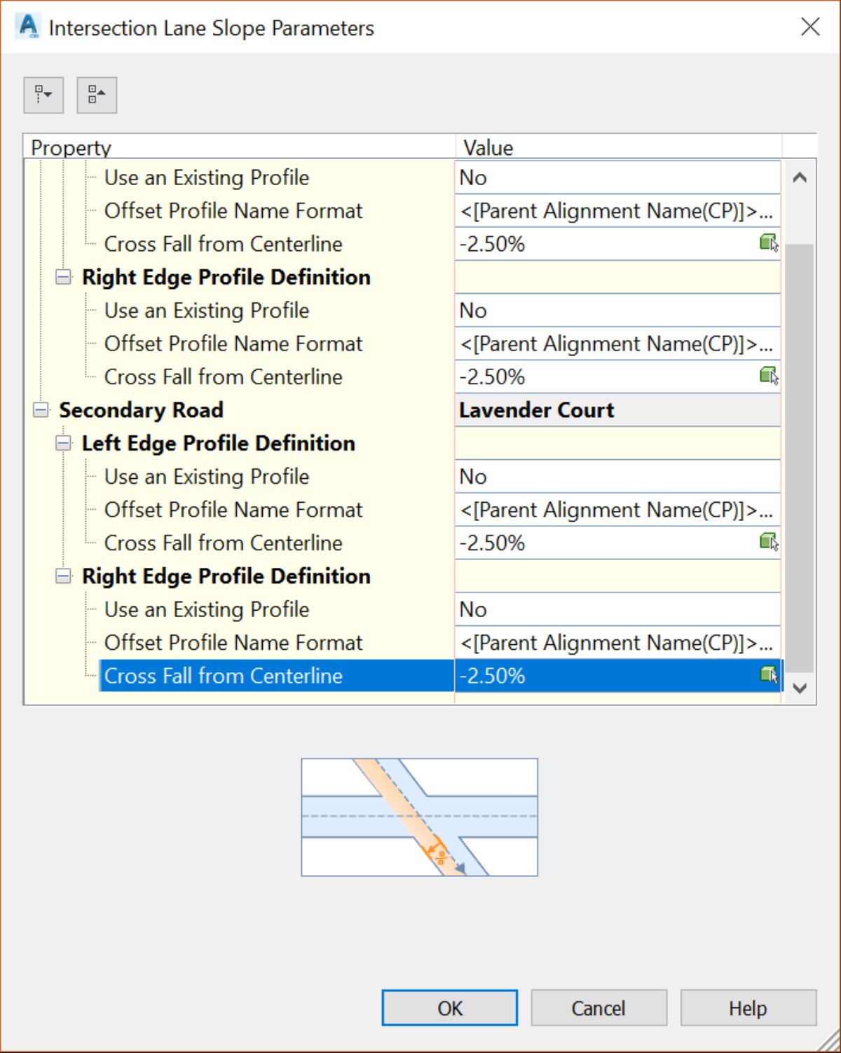
- Next, we need to adjust the lane slopes.
This is done by first clicking on the Lane Slope Parameters button,
Then by adjusting the cross fall from centerline slopes.
Change the values to -2.5% for the four lanes, then
Click OK.
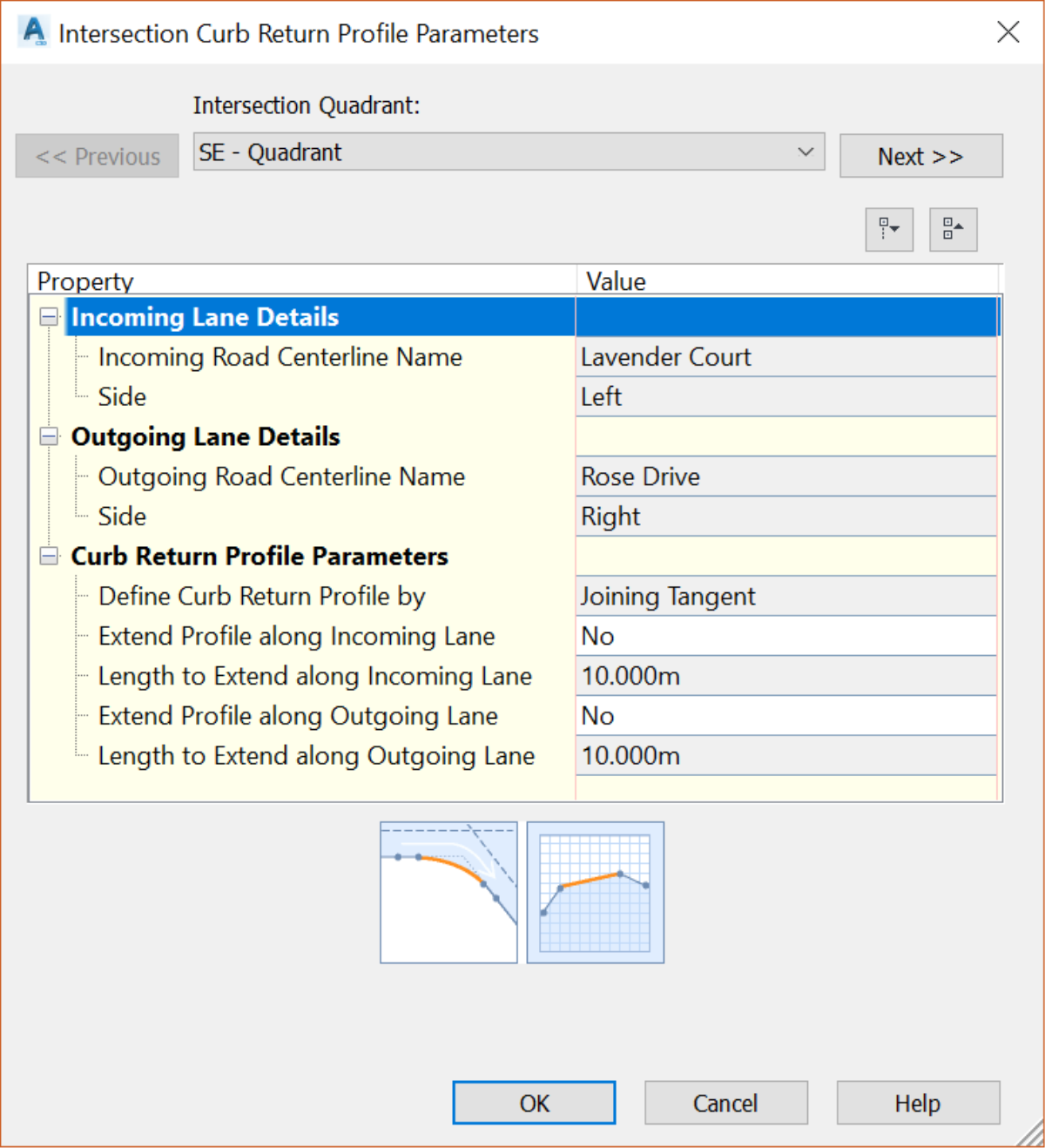
The last parameters we need to adjust on the Geometry Details page are the curb profiles.
- Click on Curb Return Profile Parameters. Here you can view and edit the parameters to extend the curb return profiles into incoming and outgoing lanes.
- Let’s change the values to 1.5m or 5ft. We don’t need to extend the intersection too far into the other streets.
- Make sure this adjustment is made for the two quadrants.
- Last, click on OK.
Next, click on next to move to the Corridor Regions page.
- Choose to create corridors in the intersection area, then add it to the existing Corridor – Flower Village.
- In the Select surface to daylight dropdown box, choose none. We will later daylight to the existing ground with our parameters. But daylighting with this particular set of assemblies may produce unexpected results. Because they are not set for our specific street.
- Leave the select assembly set to import to the default. These are default Civil 3d assemblies. We will modify them later to fit our requirements.
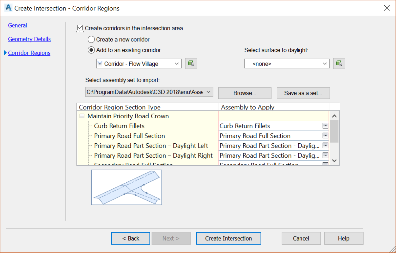
Click Create an intersection. The new intersection is created as expected.
If you only see the intersection labels, but not the intersection itself, you may need to type regenall, at the command line. As an option, use the alias REA at the command line to regenerate the drawing and show the intersection.
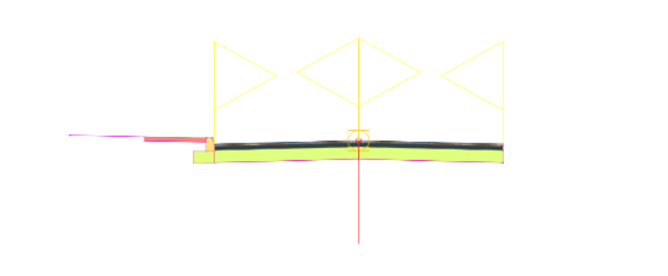
Now that the intersection is created, we need to adjust it to use our typical road cross section. Remember, we have used a set of subassemblies that comes with Civil 3D, out-of-the box. If you do a zoom extent (alias ZE at the command line), you will notice them in an empty area, far from the project site.
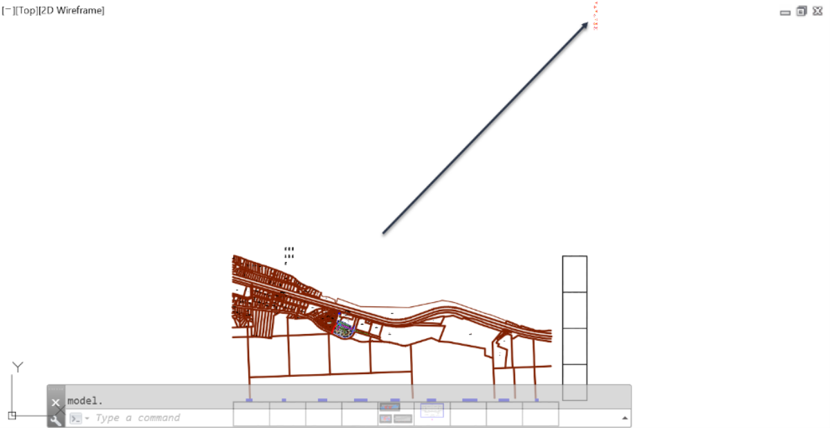
- Zoom closer and you have more information on these subassemblies.
Zoom a little bit closer...
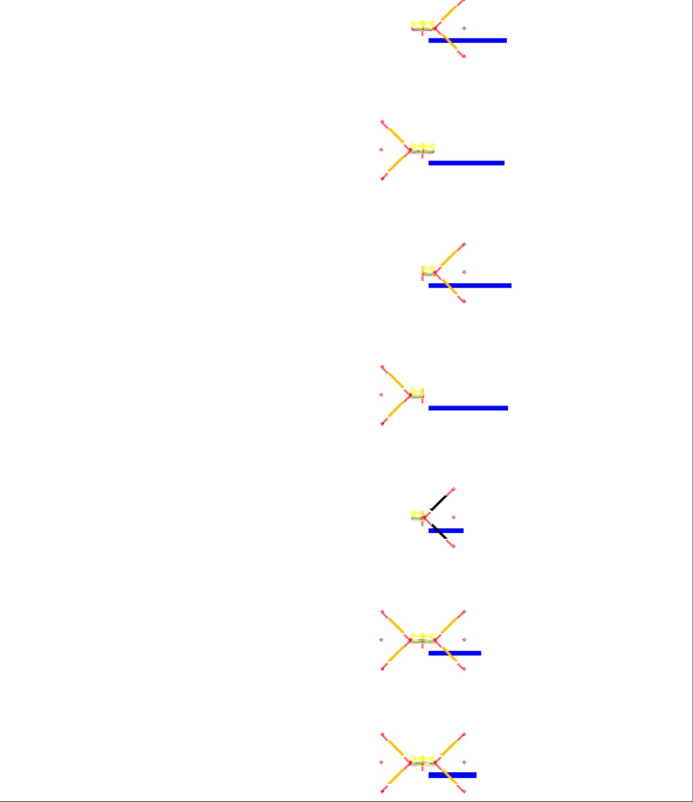
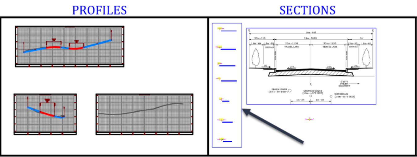
Next, let’s move them closer to our drawing objects, in a spot we can find them easily, compared to the desert they are currently located in. A good spot may be the Sections rectangle at the bottom of the drawing. Simply select them and move them like here, for example.
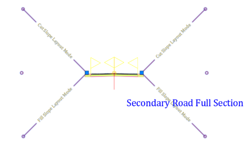
- Each one of these subassemblies is applied to the specific region of the intersection, indicated by their names. Next, our goal is to modify them to fit our specifications. So, we need to change the lane widths, curb types, add a sidewalk and landscaping strip, and delete unneeded subassemblies. Let’s start by deleting all the BasicSideSlopeCutDitch subassemblies, in all assemblies of the imported set.
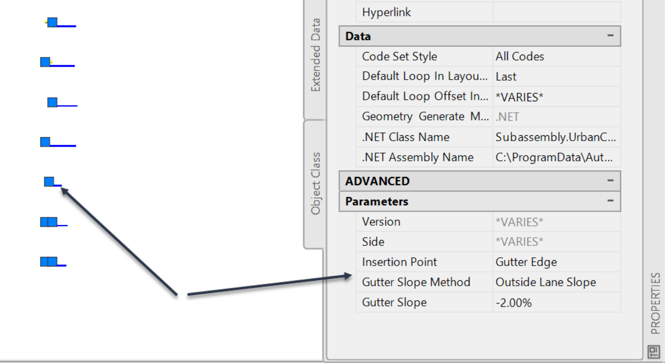
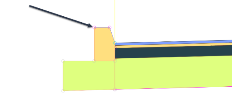
After deleting the BasicSideSlopeCutDitch subassembly, the secondary road should look as displayed.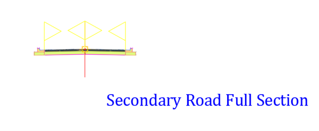 Next, select all the curbs, except the one on the Curb Return Fillets assembly. The reason we are not selecting it is that for some reason Autodesk used an R2010 version of curbs while all other curbs are R2012. So, if we select it with the other curbs, we will not have the list of parameters we want to edit, in the properties window globally. We will make this point clear in a minute. For now, just proceed and select all curbs, except for this one.
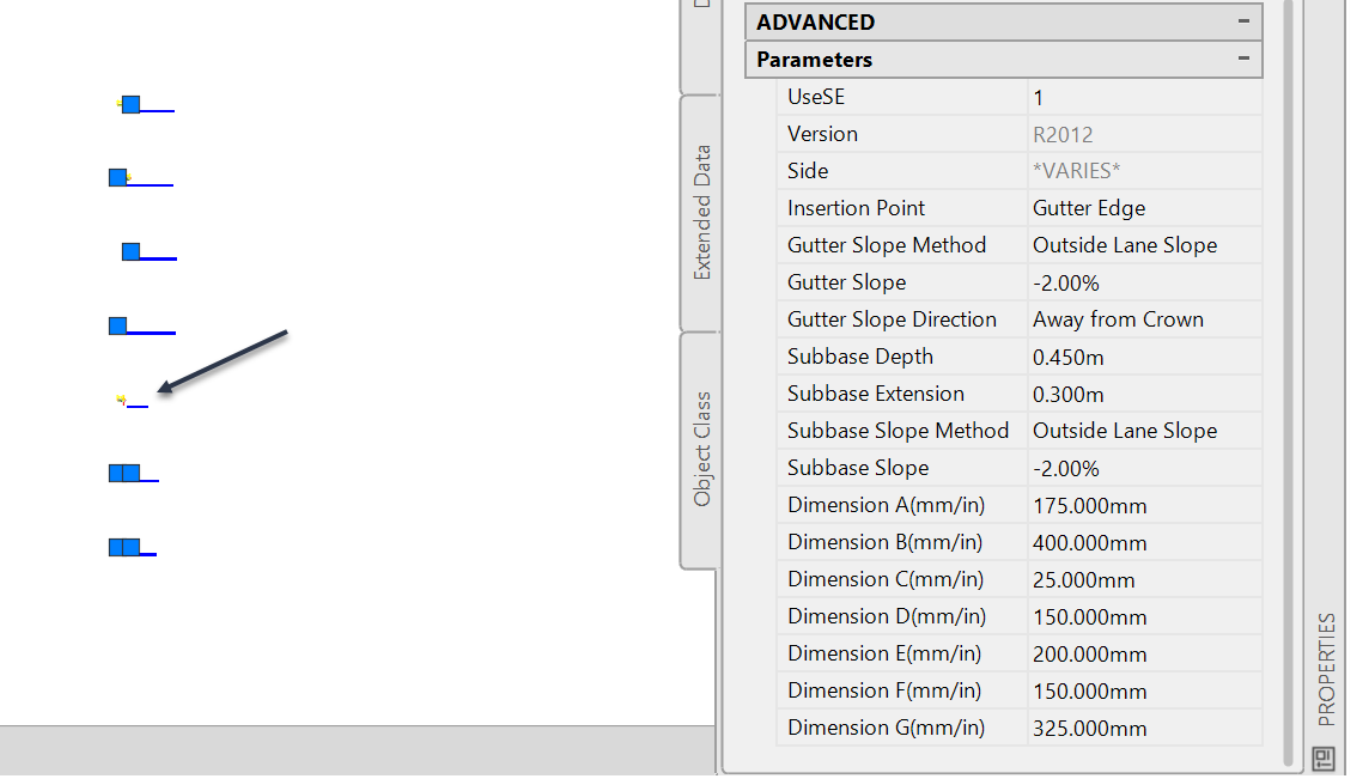
Now, we can globally edit the parameters of the curb to our specifications, as we have previously done. Don’t forget to set the B dimension to 0.0001.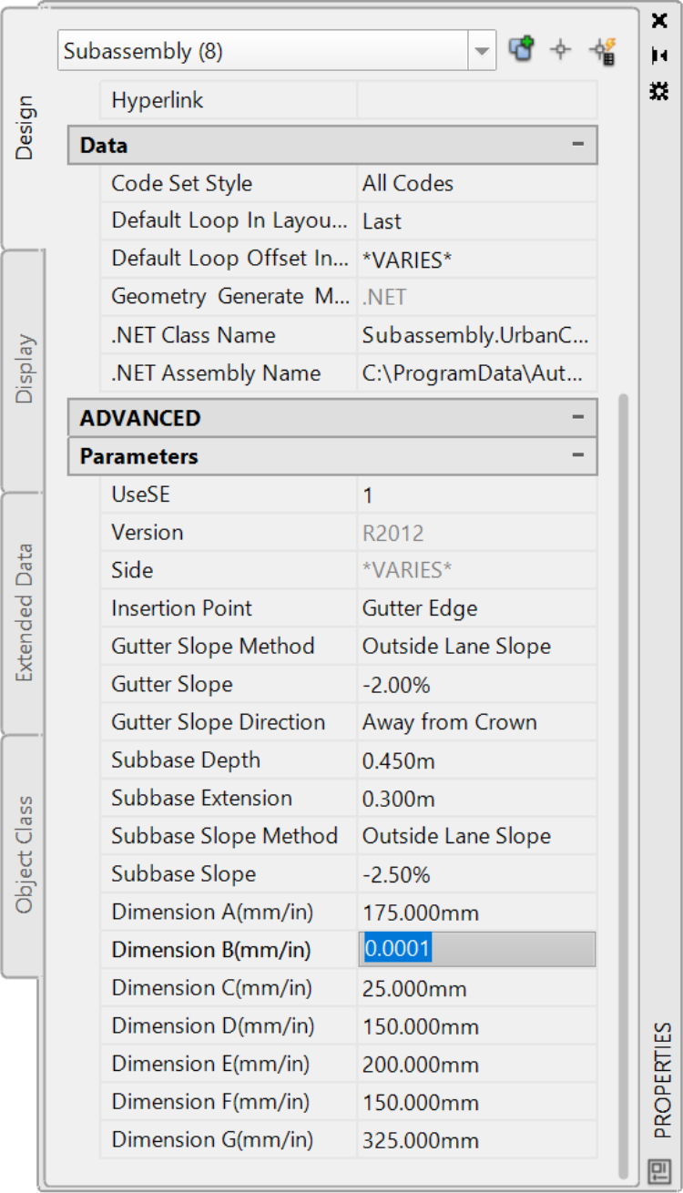
Now, let’s add the curb on the Curb Return Fillets assembly to the selection set, to illustrate what we were mentioning. Click on it to add it to the selection set. Notice how the parameters list changes and that we don’t have access to the same list of parameters. That's because all the curbs are a version R2012, except the one used for the Curb Return Fillets assembly.
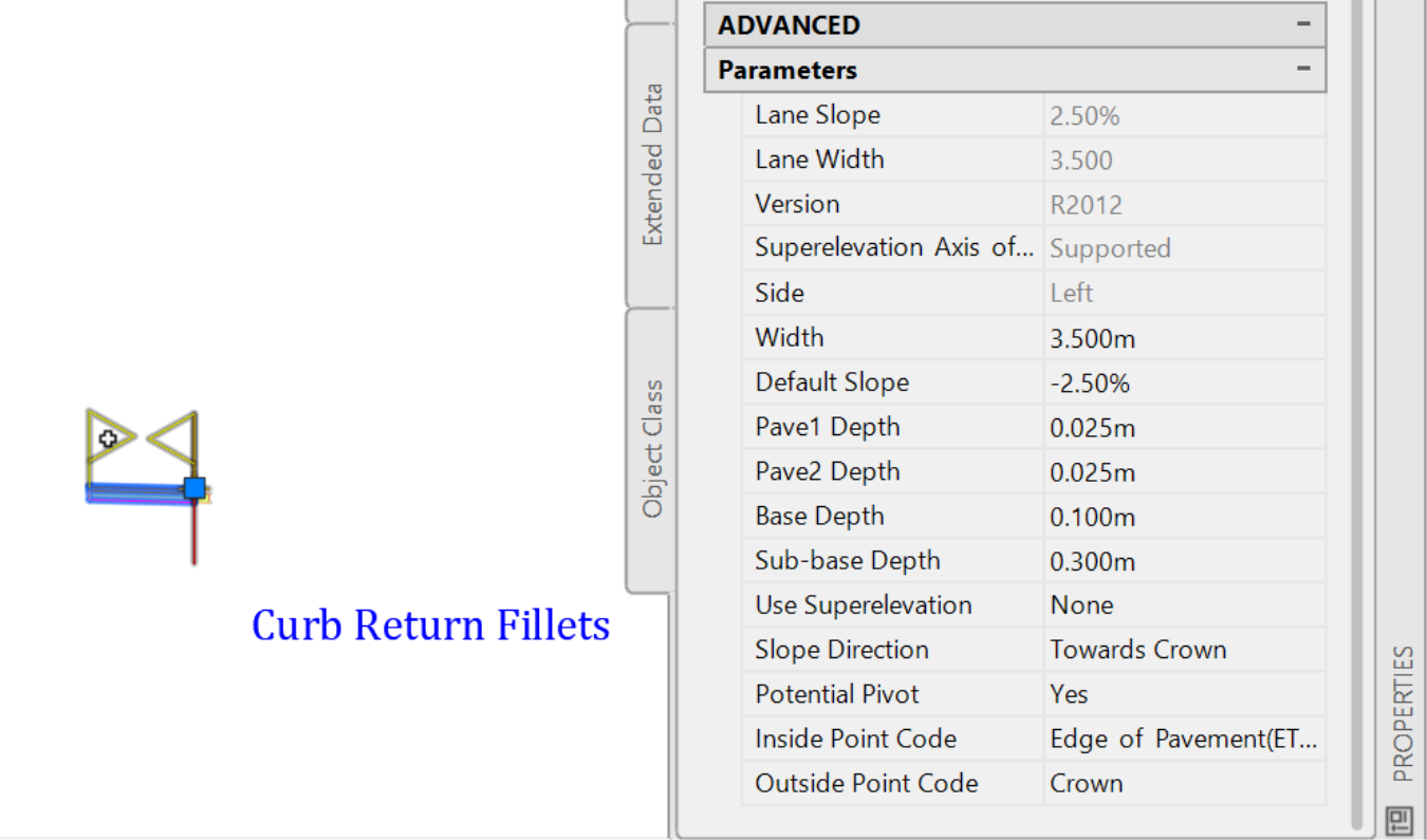
Now, press on Esc to deselect the subassemblies. Then, select that curb individually and adjust its parameters.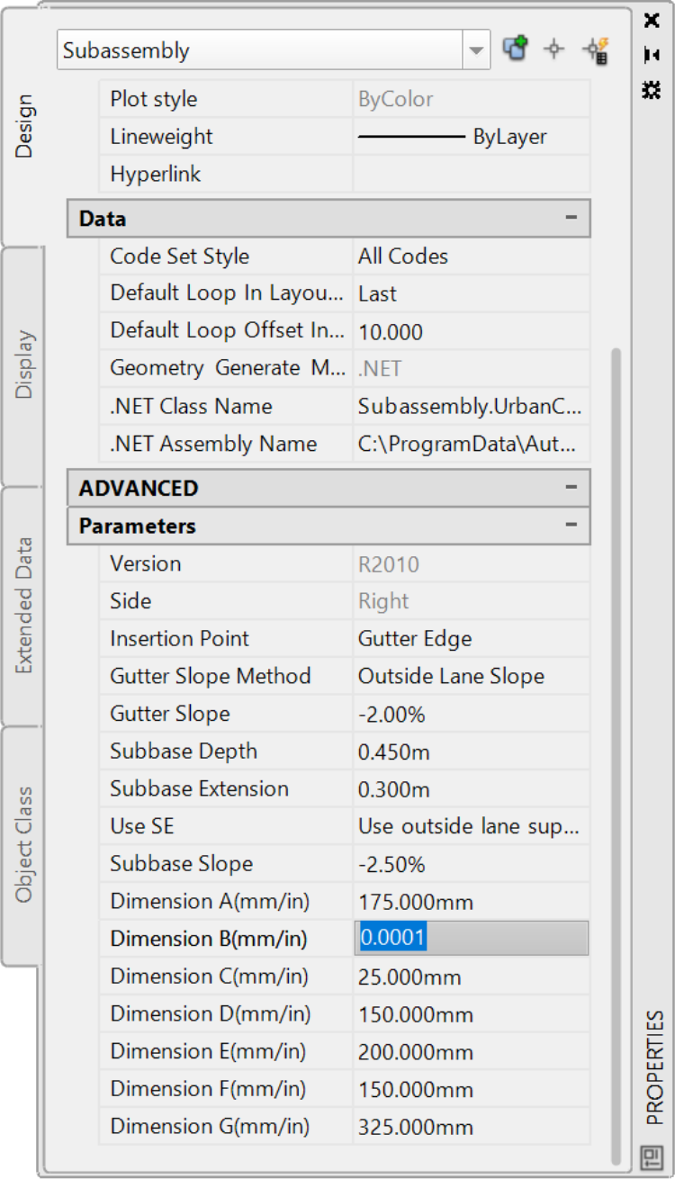
While we are still at the curb return assembly, select the lane and adjust its parameters, mainly the Slope and Width.
Now select all the remaining lanes, except the one on the curb return assembly and adjust their parameters.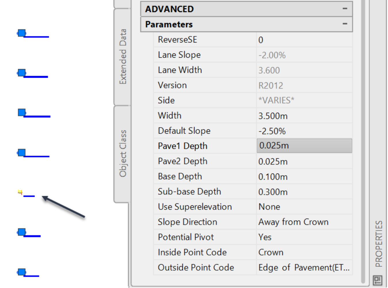
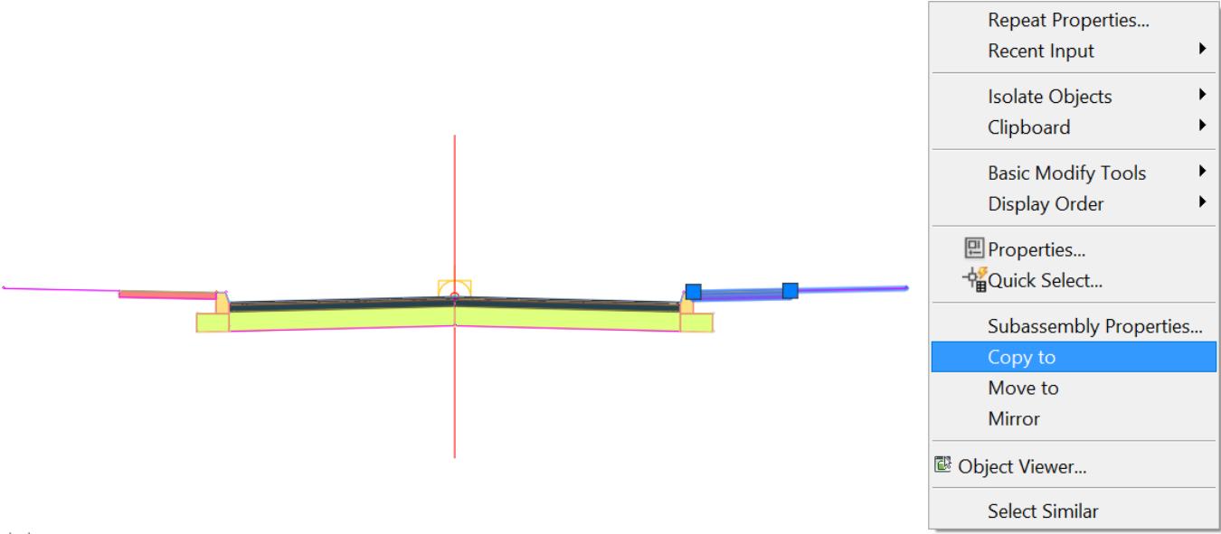
- Next, we need to add the sidewalks and the landscaping strip subassemblies to the assemblies. We can simply recreate them or copy them over from our original assembly. To copy the sidewalk and generic subassemblies, zoom to the original City of Flower Bay - Local Street assembly that we created. Then, right-click and select Copy to
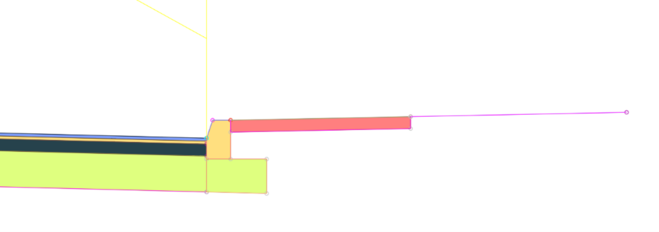
Next, zoom to the set of assemblies and click on the top back of curb point to attach the two subassemblies we have copied. You need to be mindful of the side, left or right, you have copied the subassemblies from. Do not copy subassemblies to the opposite side.

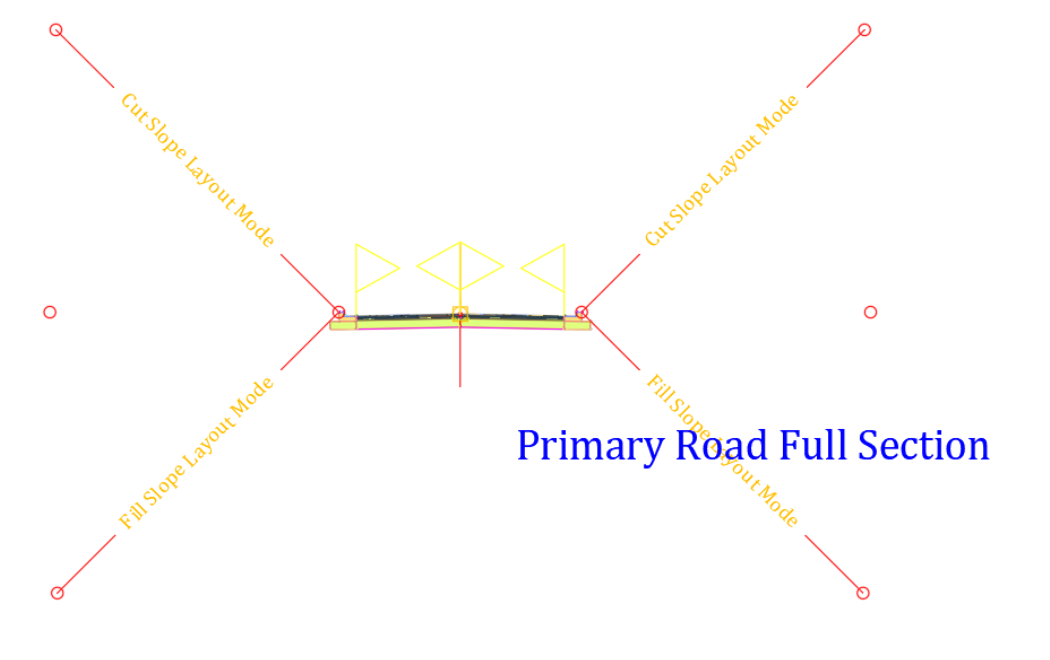
 Repeat the process and duplicate the assemblies you have just copied to all other curbs on the same side. On the right side, we will copy them to the following assemblies: Secondary Road Half Section - Daylight Right, Curb Return Fillets, Secondary Road Full Section and Primary Road Full Section.
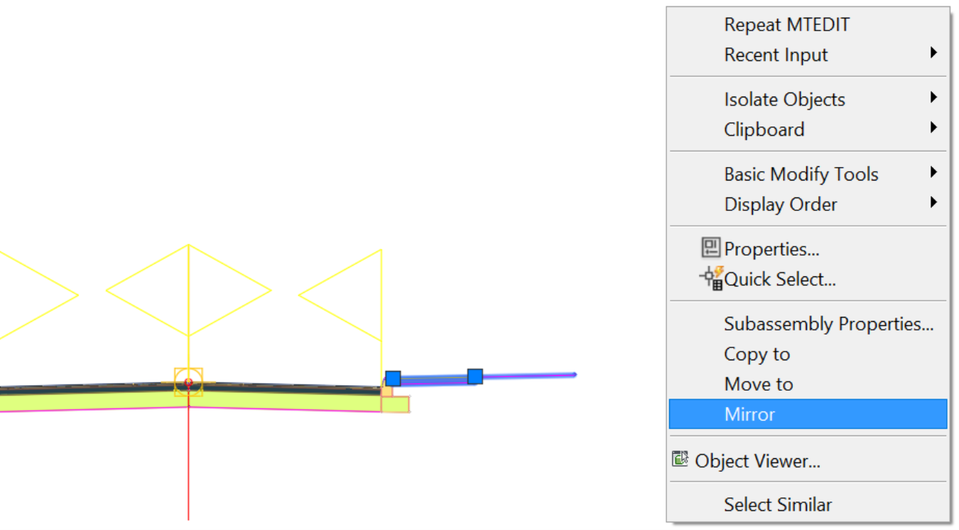
For the left side, select two subassemblies (the sidewalk and the generic one) on the right, right-click and select Mirror. Then click on the top back of curb points, on the opposite side.
 Repeat the same process,
- by mirroring from the right; or
- by copying the sidewalk and generic assembly to the curbs on the left.
When done, you would have attached them on the left to Primary Road Part Section - Daylight Left, Secondary Road Half Section - Daylight Left, Secondary Road Full Section, and Primary Road Full Section.
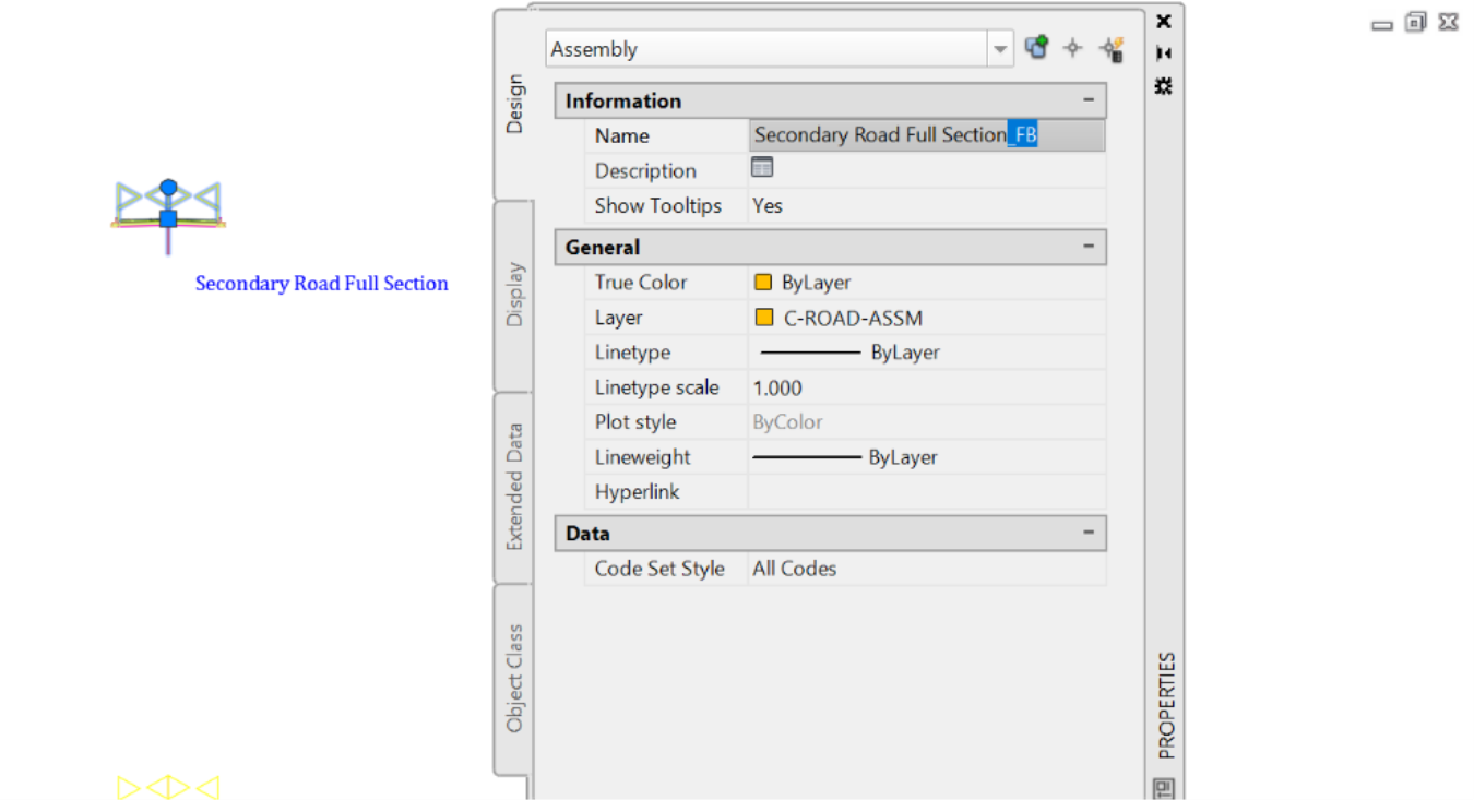
We will now rename the typical sections to create a set that can be reused to create an intersection later in this project or another one. To do that,
Add a suffix or prefix of your choice to each assembly. For example, we can add the name of the municipality at the end of the assembly, such as adding the suffix FB for Flower Bay.
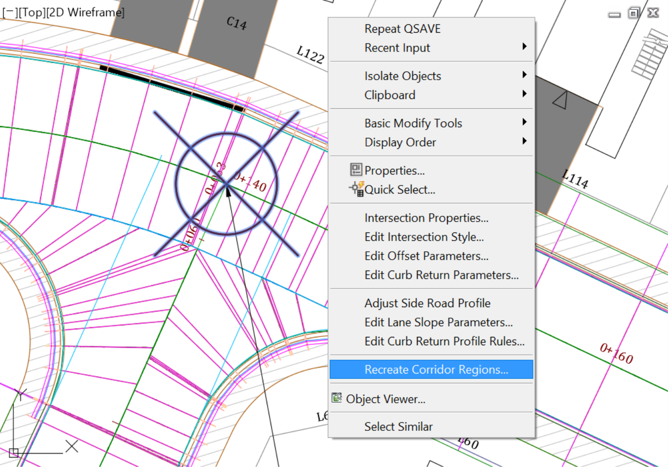
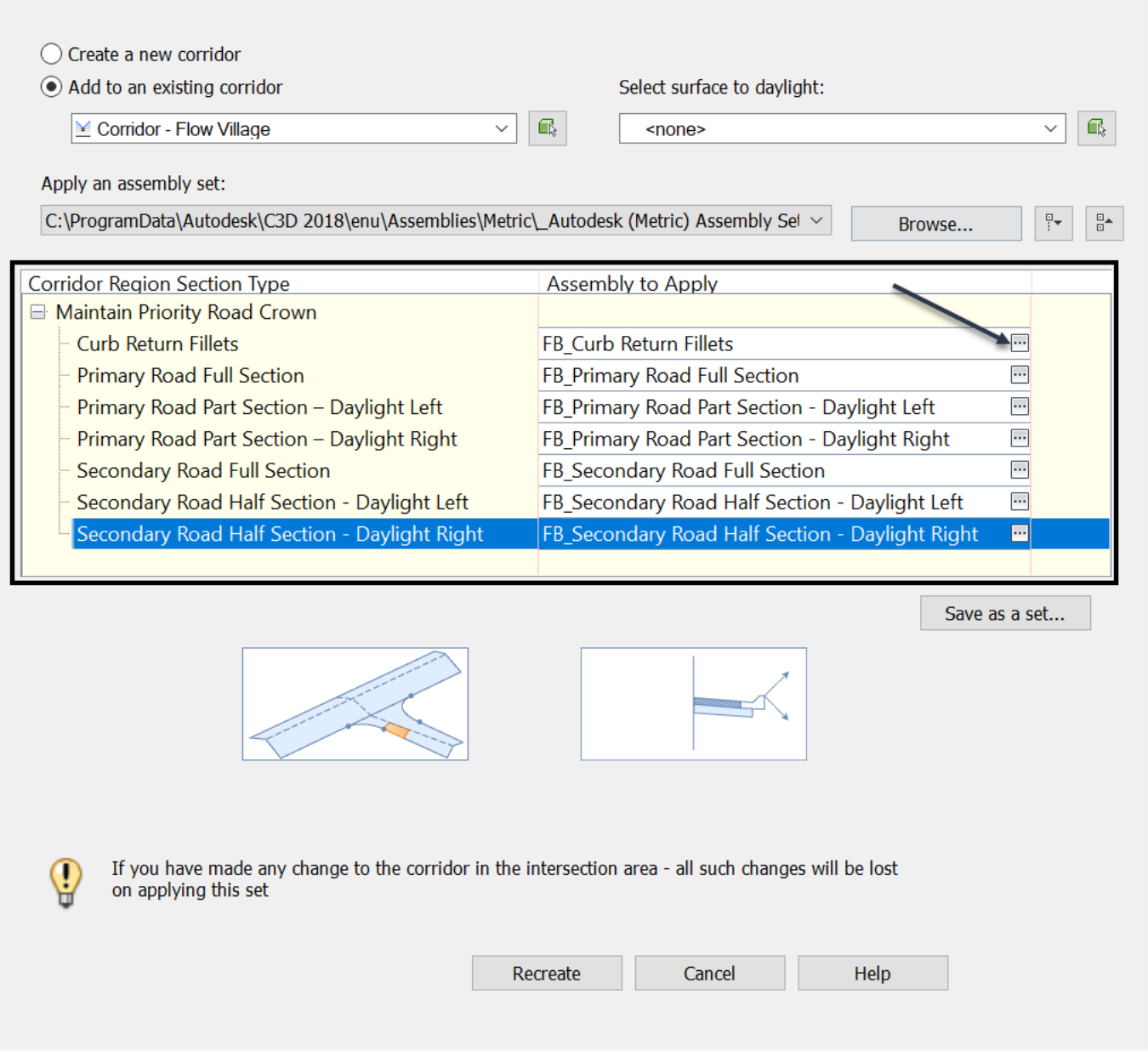
Repeat this process for each of the assemblies. Select them and add a suffix.Now, let's create a set of assemblies for future use. Select the intersection symbol. Right-click and select Recreate Corridor Regions.
Replace each subassembly with the renamed ones, by clicking on the three dots icon to the right of each assembly.
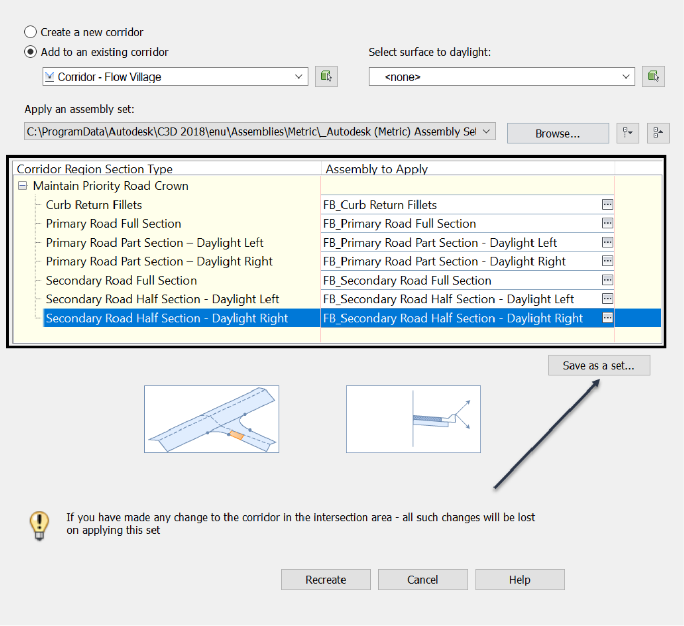
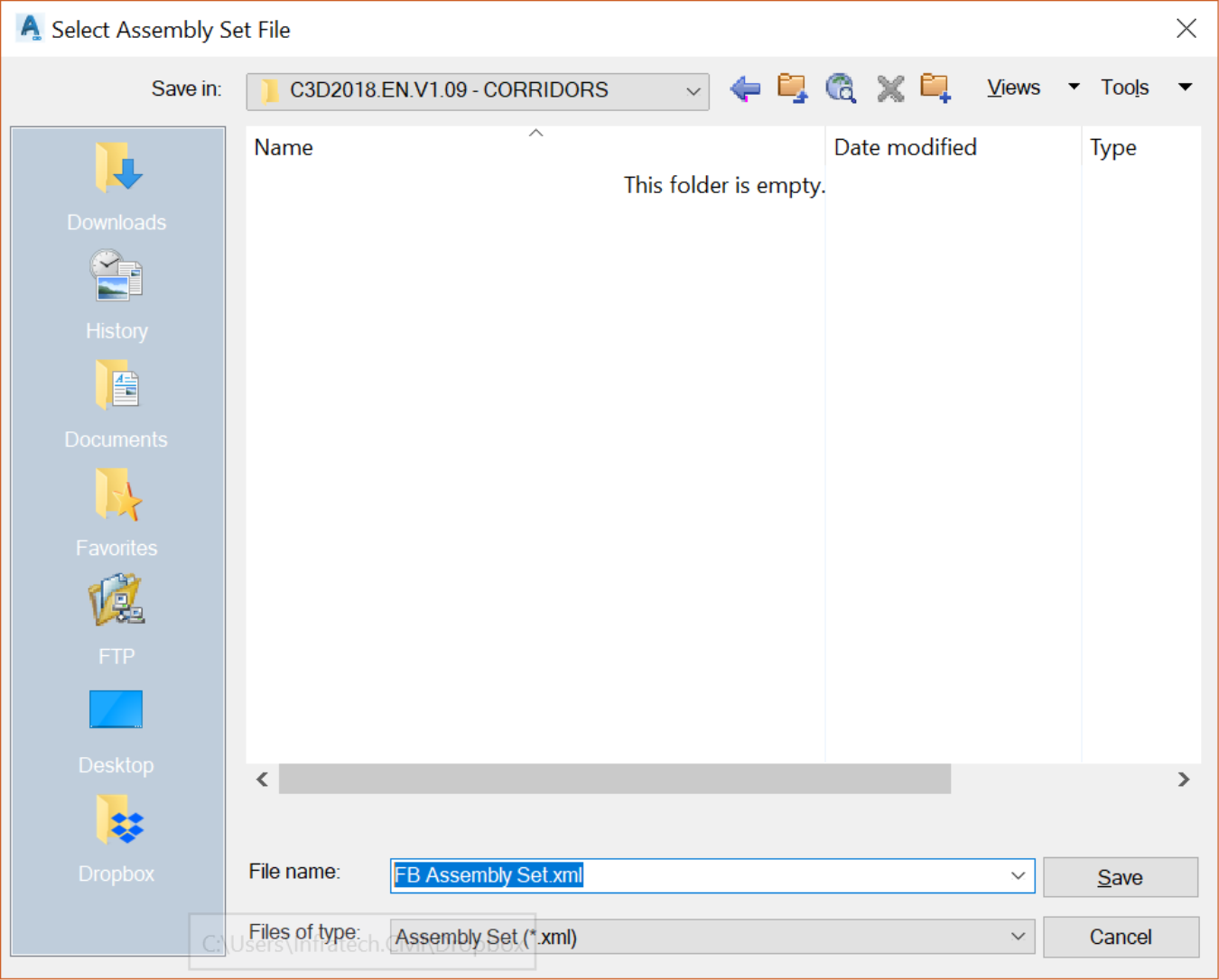
Once all subassemblies have been replaced, save the set under a new name in an accessible folder for future use.
Now, browse to specify the folder to save the assembly set, in our corridor practice folder, for example.
Once you are back to the Intersection Creation window, click on Recreate. The intersection is now re-created with the new assemblies and their specifications.
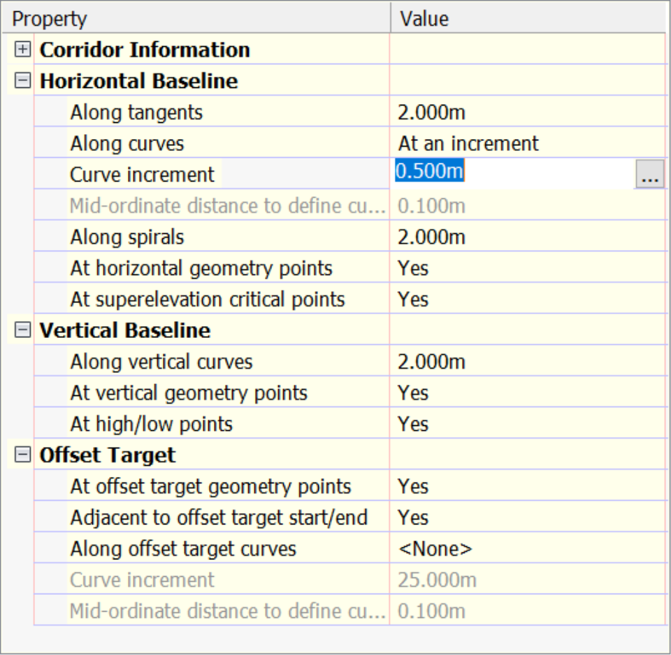
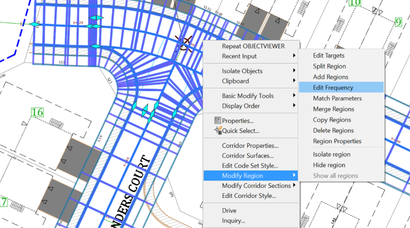
We can now adjust the intersection by tightening the frequencies. To do so, select the intersection, right-click and select Modify region, then Edit Frequency.
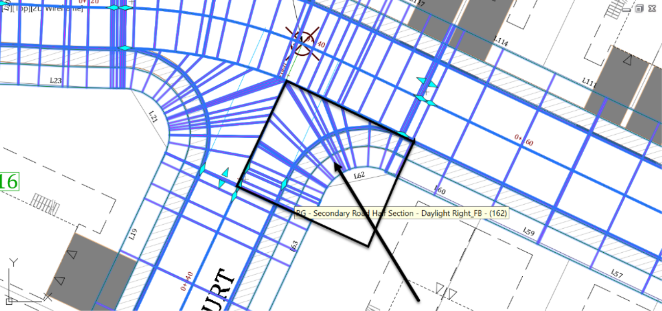
Next, click inside one of the corridor quadrants, the southeast one for example.
Afterward, in the frequency editor change the Curve Increment to 0.5m or 1.5ft.