-
Get It
$19.99
$19.99Civil 3D Essentials Book and Practice Files
Civil 3D pipe network layout: A step by step tutorial guide
Introduction to Civil 3D pipe network layout
Firstly, what is a Civil 3D pipe network layout? Well, let's find out in this online training course. Certainly, this step by step tutorial is a part of the Civil 3D essentials book and how-to manuals.
Working with Civil 3D pipe network layout
Pipe networks can be created using existing Civil 3d objects like 3D polylines and feature lines. We can also design them by layout using the Pipe Network Creation Tools. First, let’s create the storm sewer network with the by object method.
- Open the 10.01-Pipes dwg file in Lesson 10 practice folder.
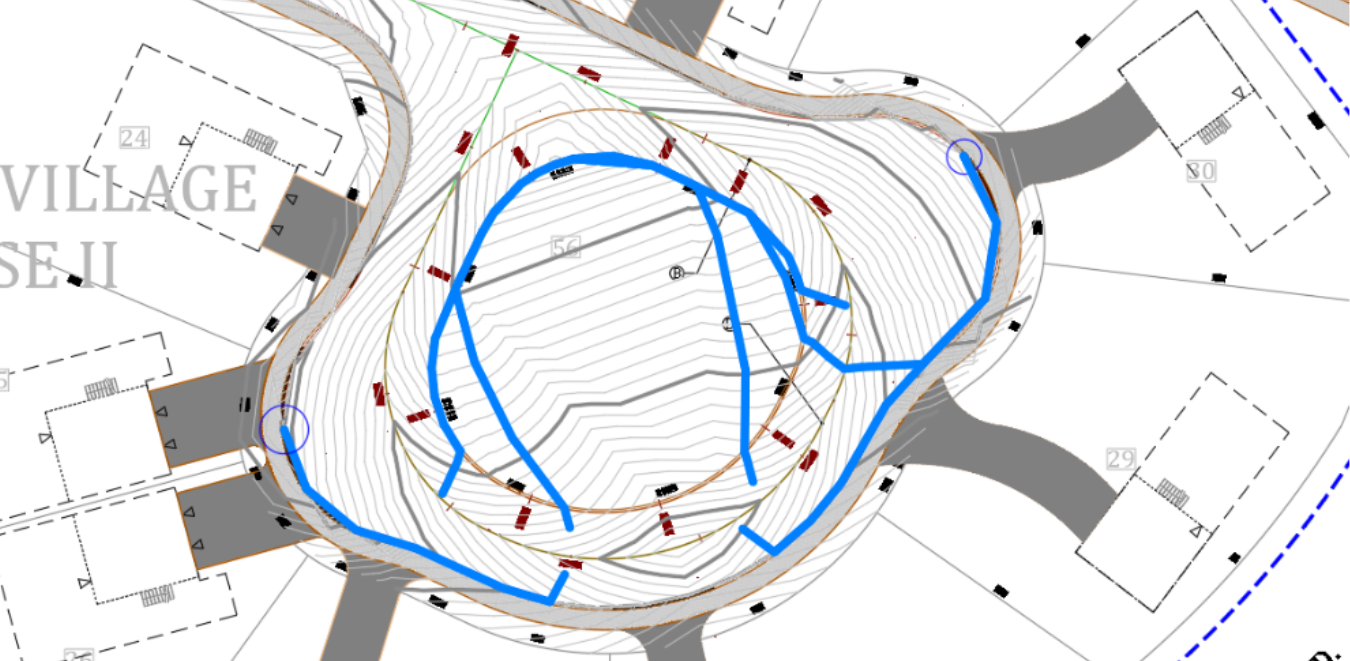
- In previous lessons, we have already designed a proposed surface for Roses Drive, using a proposed profile. The profiles will also allow us to determine low and high point locations. As a requirement of the stormwater system design, we need to make sure that we put catch basin inlets at every low point, on the street. We can thus collect rainfall runoffs. To identify these points, we can use the profile and create low point labels on the street alignment. But an easier and more visual way is to use the Water Drop tool we talked about in the lesson on surfaces. Let’s run the Water Drop command by selecting our design surface. It’s worth mentioning that the design surface is still temporary as we haven’t done any grading at the lot level yet. However, we are done with the street portion of the surface. You can see the finalized corridor by turning on the C-Road-Corridor layer, from the layer manager. Look at it and turn the C-Road-Corridor layer backoff.
- Let’s check out the locations of these low points on the plan. Each time we locate a low point, we will create a circle to mark the location temporarily. In the drawing, select the corridor surface.

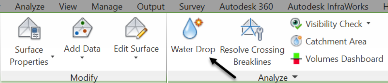
- On the ribbon, run the Water Drop command.
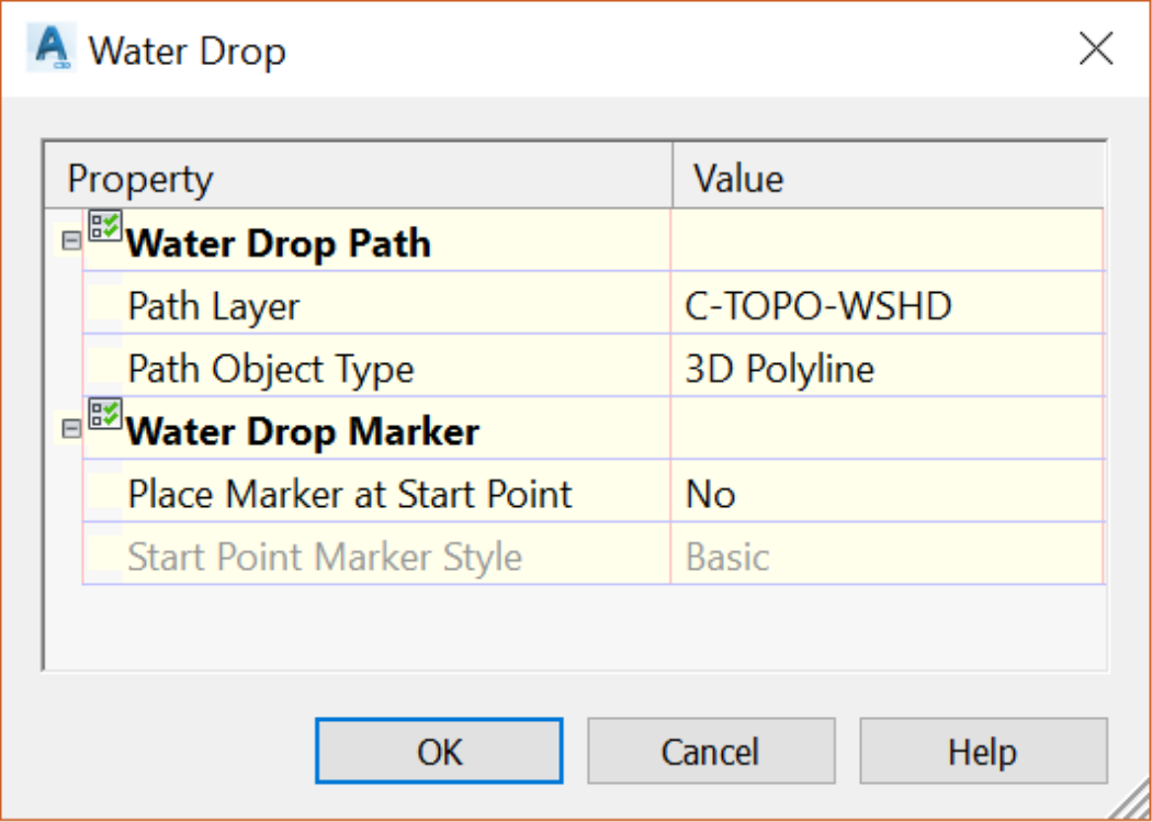
- In the next window, assign a layer, probably the C-TOPO-WSHD watershed layer and a Path Object Type. Then click on OK.
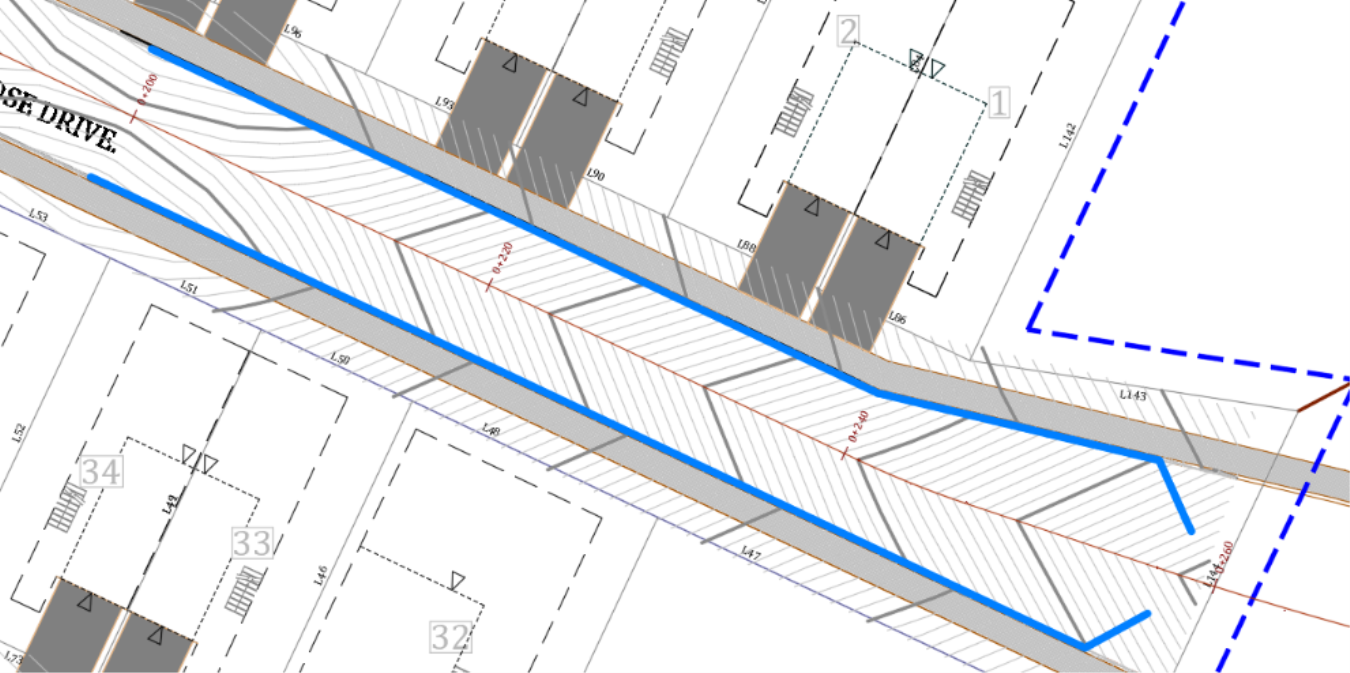
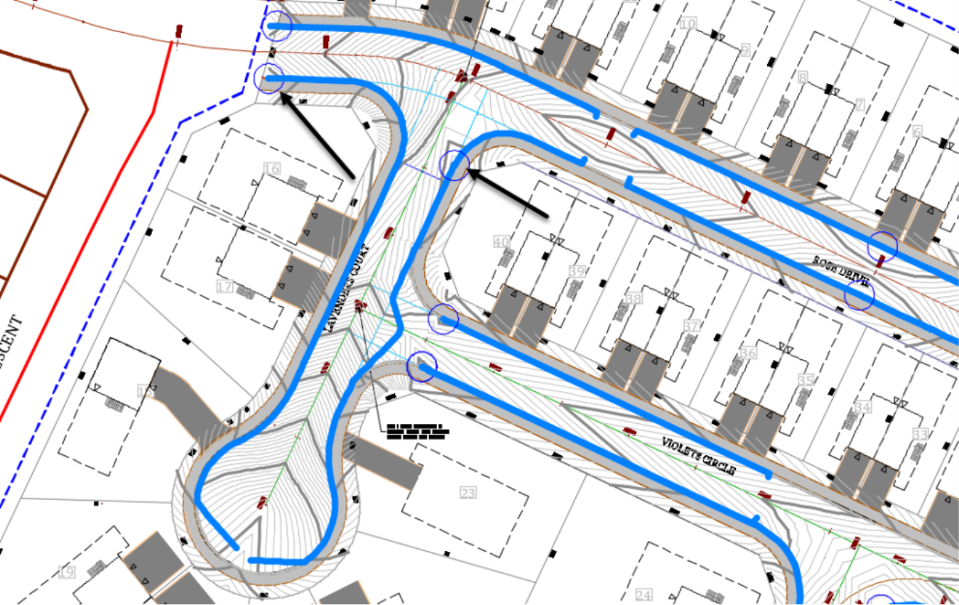
- Next, click on the eastern end of Rose Drive, on both sides of the centerline, around station 0+260m or 0+850’. You will notice a flow line running along the curb line on both sides of the road. These represent the path that a water drop would take along the street all the way to the lowest point in the area.
- To add a low point label, Create two circles at the ends of the flow paths.
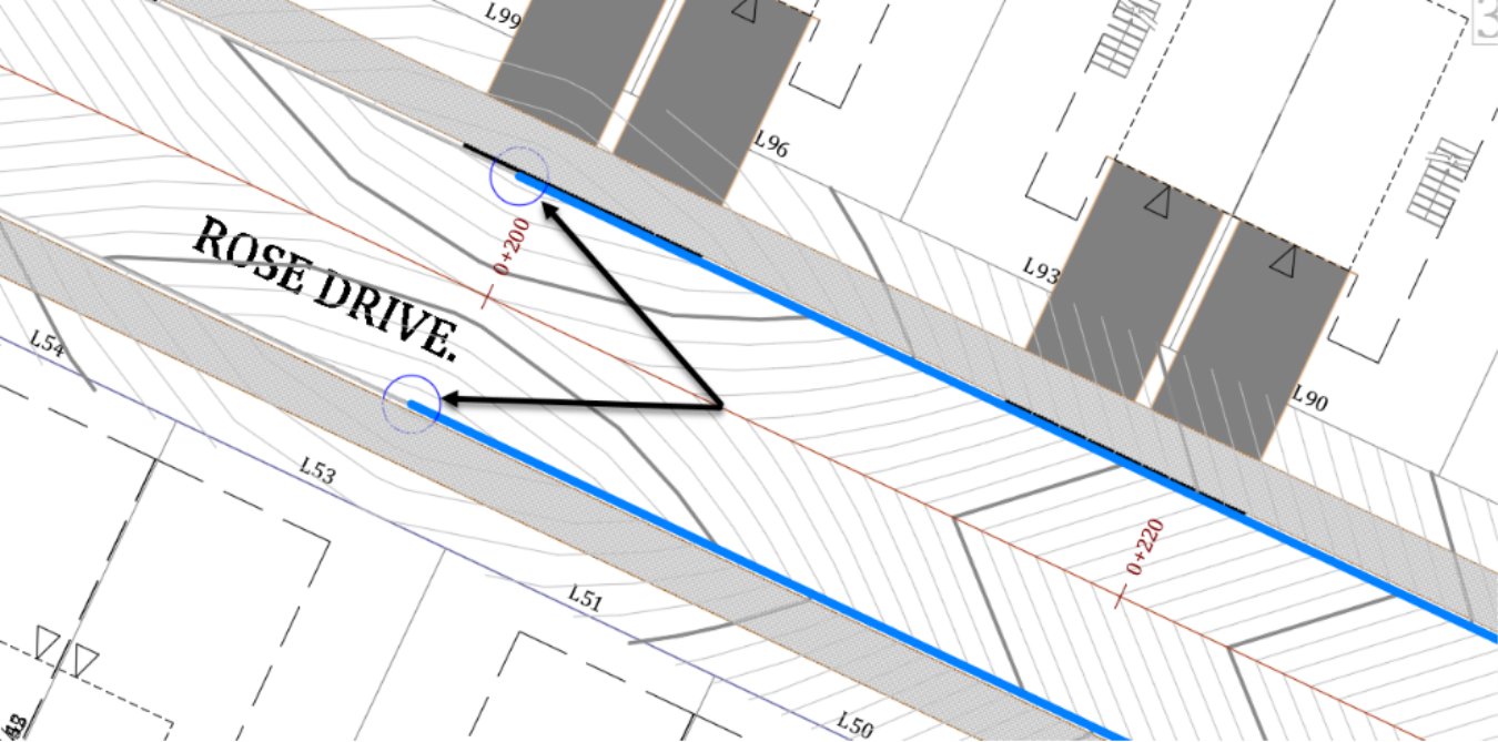
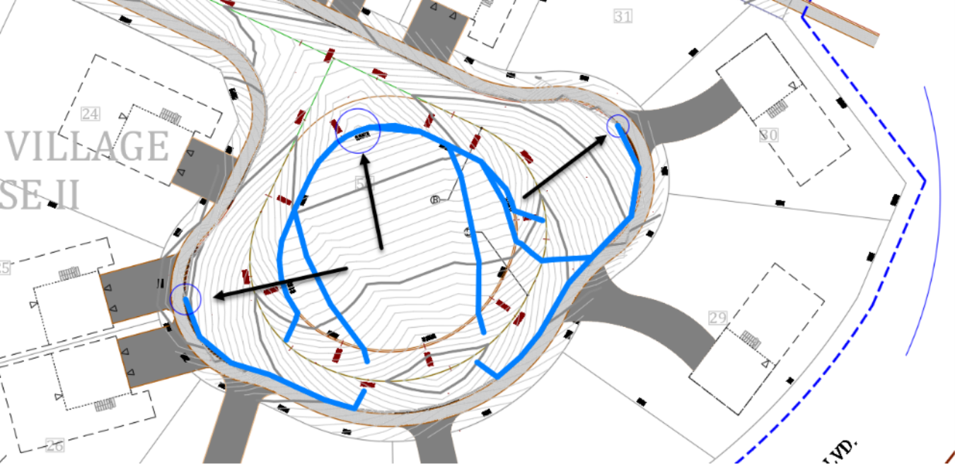
- Next, create a water drop flow path on the other side of the street. Looking at the contour lines, there is a high point around station 0+160m or 0+525ft. Let’s click on both sides of the high point and both sides of the street centerline.
-
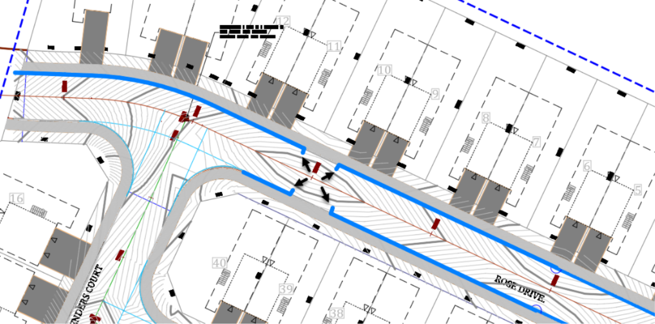
By examining the flow paths from the last couple of points, we can conclude that:
- On the north side of Rose Drive centerline, water is flowing toward the western end of the site. Therefore, a catchbasin needs to be installed at that station on the north and south side of the street centerline, exactly at the site boundary. On the south side of Rose Drive, the flow path is stopping approximately at the start of the southeast quadrant of the intersection.
- On the north side of Rose Drive centerline, water is flowing toward the western end of the site. Therefore, a catchbasin needs to be installed at that station on the north and south side of the street centerline, exactly at the site boundary. On the south side of Rose Drive, the flow path is stopping approximately at the start of the southeast quadrant of the intersection.

- Now, create the three circles at the low points for future catchbasins.
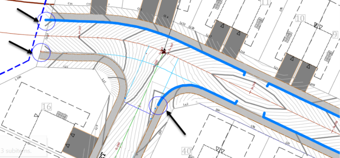
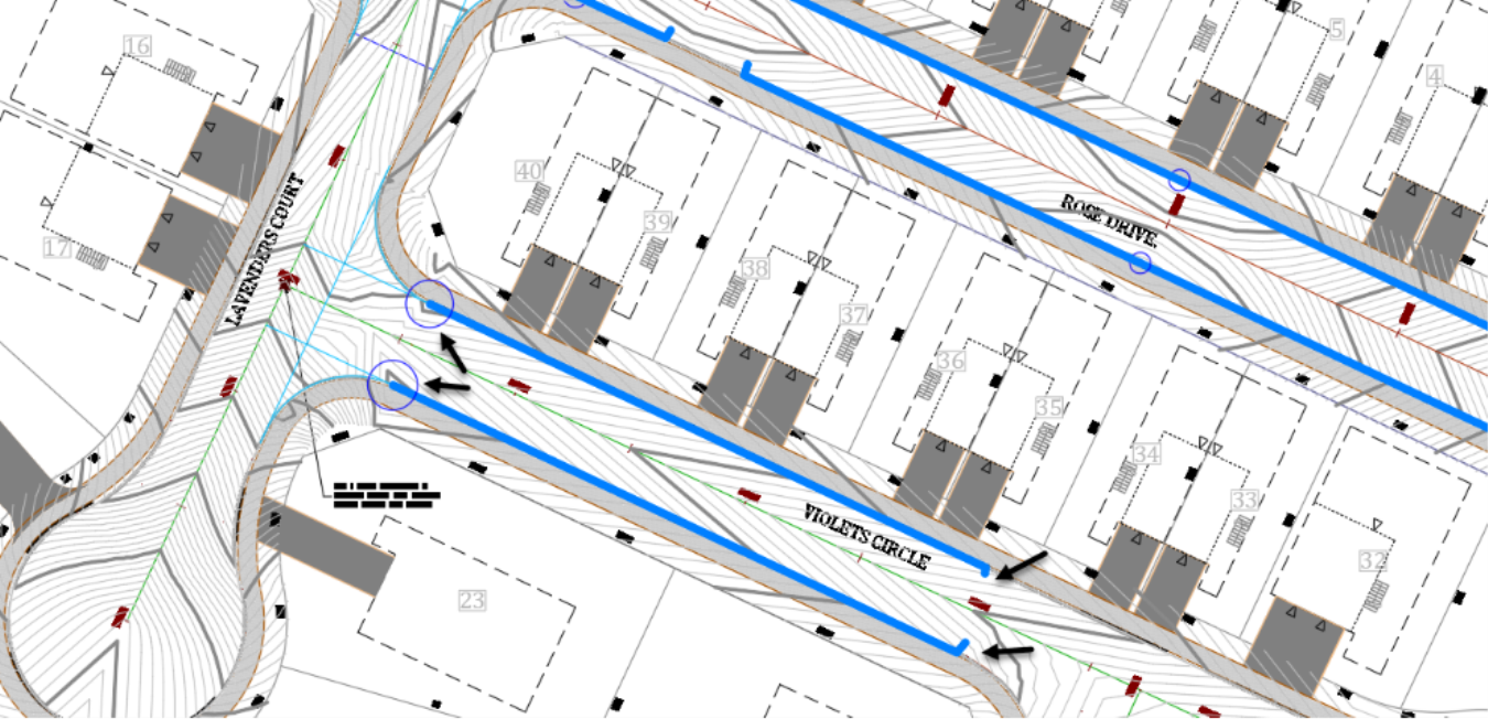
- Next, repeat the same process for Lavender Court and Violets Circle, starting at the end of the cul-de-sacs. For example, for Violets Circle, let’s put a couple of water drops on each side of the high points around station 0+132m or 0+430ft. You will notice the two low points in the cul-de-sac.
- If you create a drop on the north side of these two locations, you will notice a flow path going through the island, to the low point on the other side. That’s because we have not refined the elevations enough for the curbs to have enough effect and curb the flow. However, the grading is looking good for now, as we can clearly identify the low points.
- Now, create the third circle in the cul-de-sac for the grading.
- Next, create the Water Drops, on the linear section of Violets Circle. The low points are located all the way to the start of the curve at the intersection with Lavender Court. These will be two ideal locations to install catchbasins and catch all the flow coming from up top.
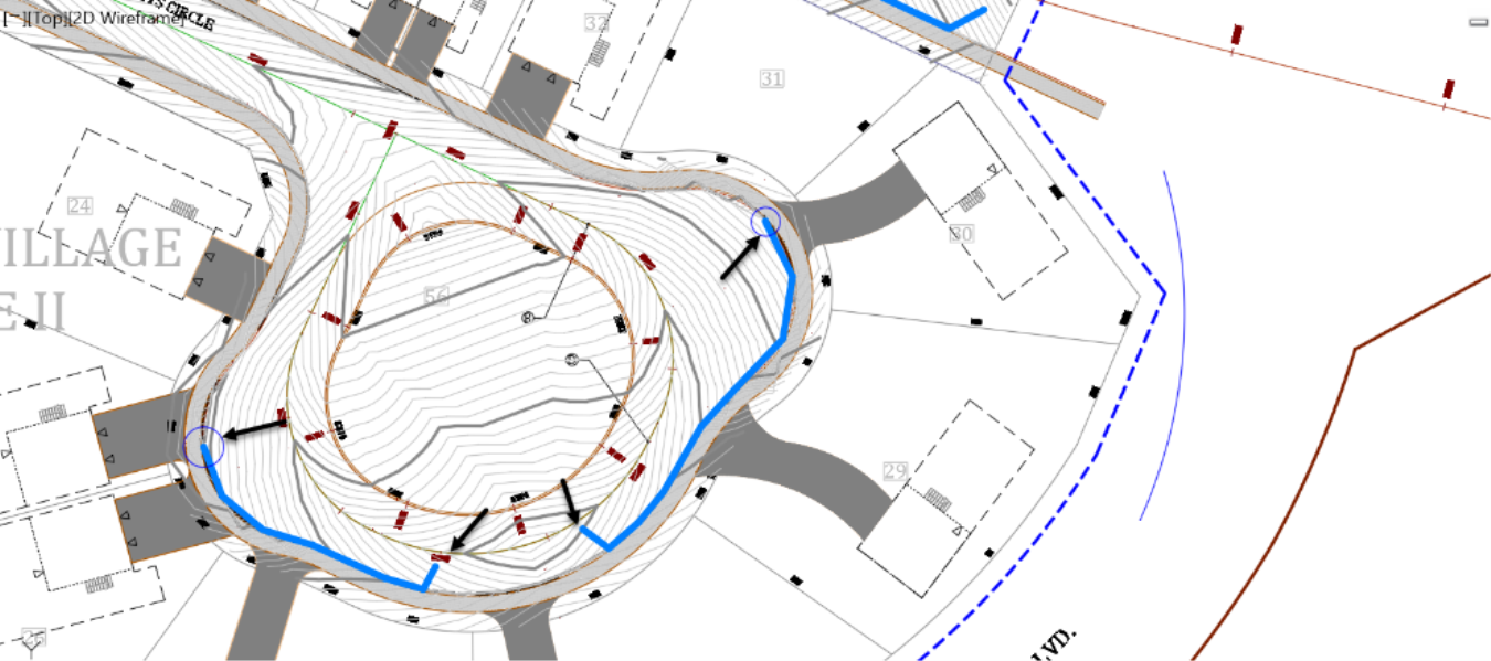
- Finally, let’s create the water drops in the cul-de-sac area of the Lavender Court. Create two water drops on each side of the high point located at the top of the cul-de-sac.
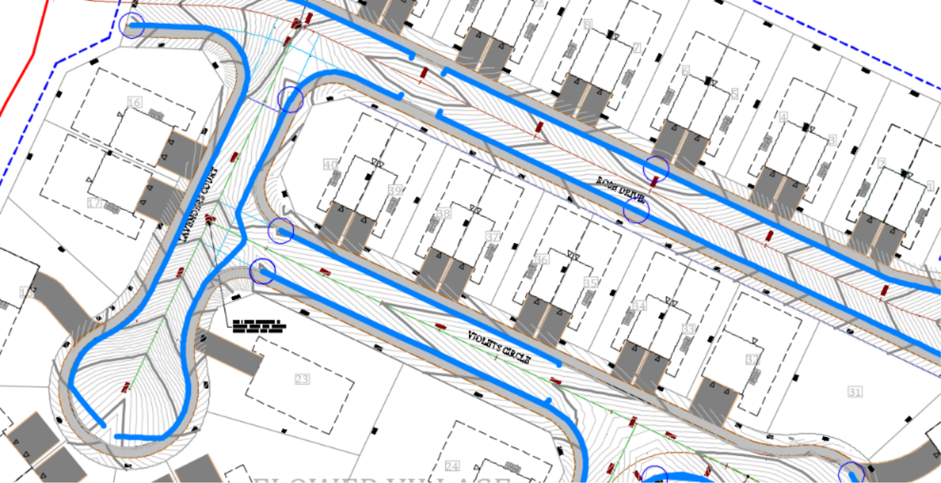
- You’ll notice that the rainfall runs off from the cul-de-sac all the way to the last manhole on the west of Rose Drive, on one side. And on the other side, to a low point, at the start of the curb return in the southeast quadrant of the Rose Drive – Lavender Court intersection.
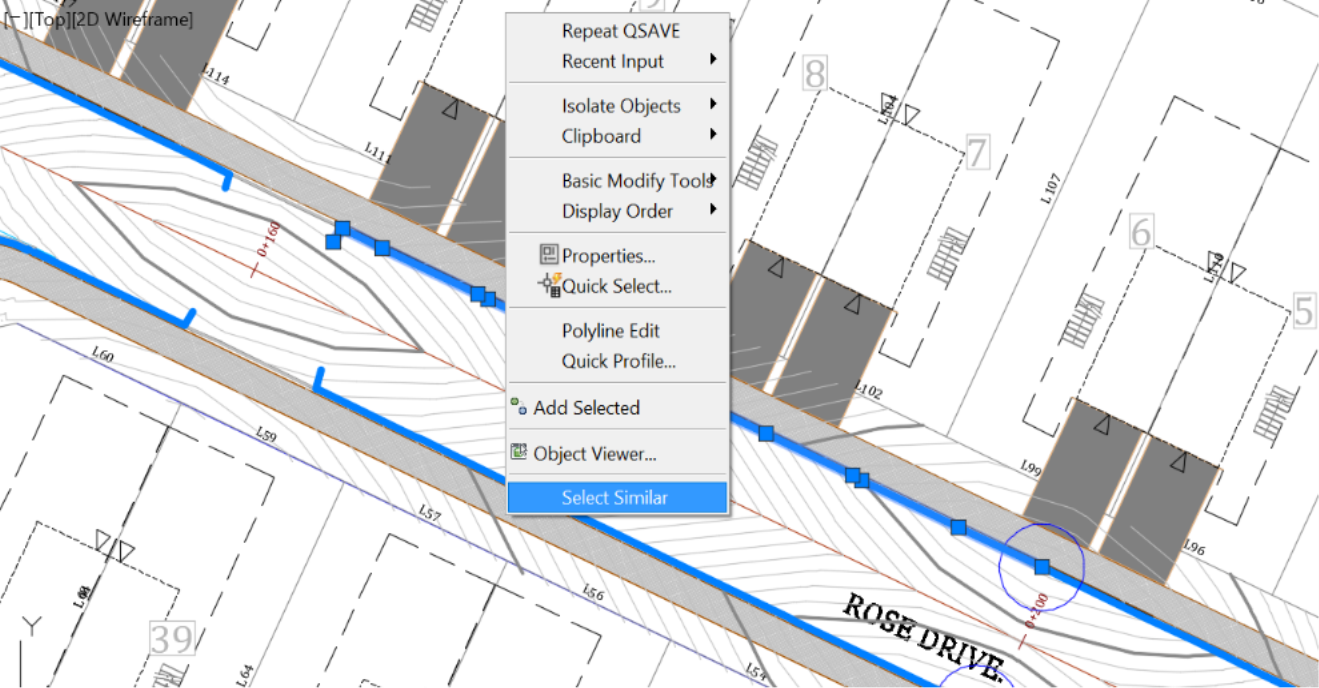
- This process gives us a preliminary idea of how to lay out our storm sewer system. Before moving on to the next thing, let's clean up the clutter we have created with the water drop lines. Select one of the lines, right-click, select similar and delete from the keyboard. The select similar allows selecting entities sharing similar properties. We facilitated their selection by creating the water drop lines using 3D polylines and putting them on the watershed layer. Few other objects have these properties. On the other hand, we will not delete the circles, as we still need them to place our catchbasins
.