-
Get It
$19.99
$19.99Civil 3D Essentials Book and Practice Files
Civil 3D Pipes Layout Tools: A step by step tutorial guide
Introduction to Civil 3D
Firstly, what are the Civil 3D Pipes Layout Tools? Well, let's find out in this online training course. Certainly, this step by step tutorial is a part of the Civil 3D essentials book and how-to manuals.
Working with Civil 3D Pipes Layout Tools
The second option to create and edit pipe networks is by using the Pipe Creation Tools. Using the tools, we can modify an existing network or create a new one or set initial pipe network creation parameters. We will have options to assign names, descriptions, layers, parts and much more. Just like we did with the creation by object method.
Let's use the Pipes Layout Tools to modify an existing system, the Storm Sewer network, and create a new one, the Sanitary Sewer.
We will modify the Storm Sewer network by adding the catchbasins and their leads to the manholes.
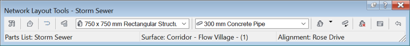
- First, select any part belonging the Storm Sewer, right click and select Edit Network.

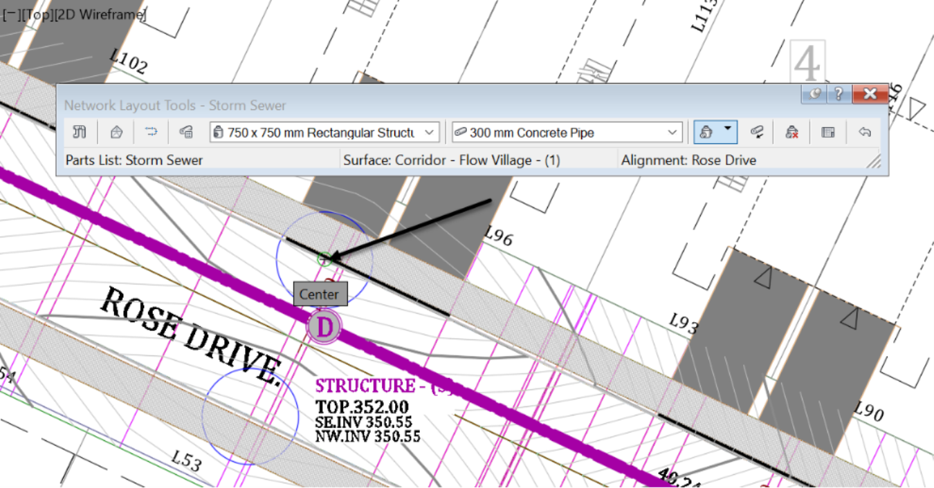
- The Network Layout Tools opens and comes already set with the network parameters like the surface, the alignment, and the part family to use. We can still change them if needed.
![]()
- Let's explore a few of the Pipes Layout Tools. First is the Pipe Network Properties.
![]()
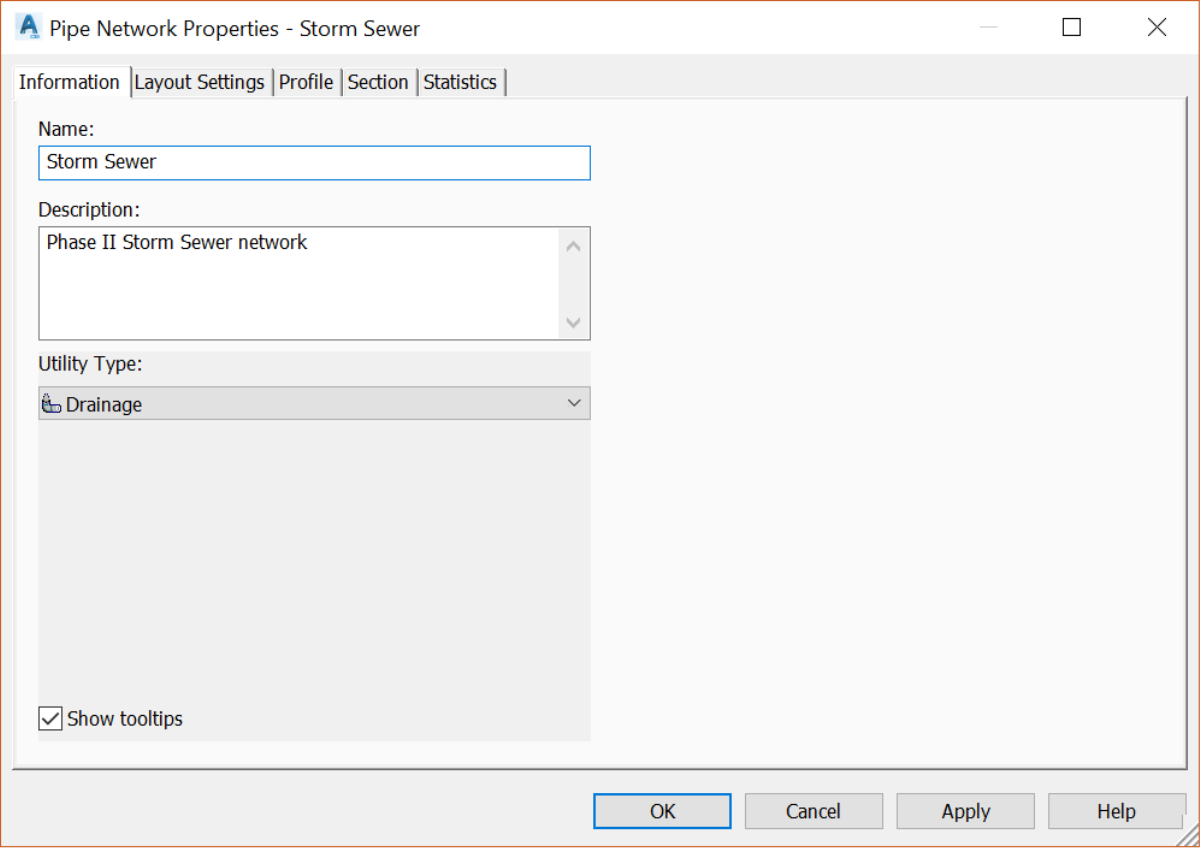
- Once you click on it, you can change the Network name and description from the Information tab.
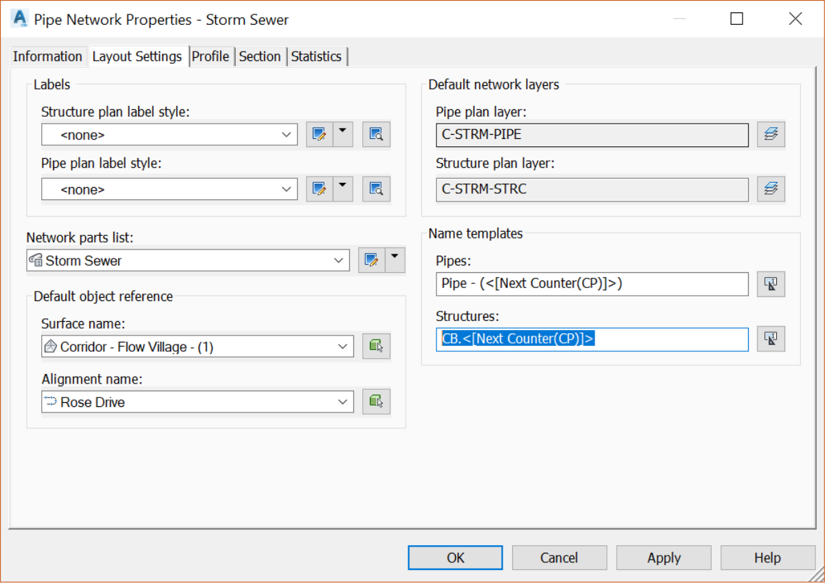
- On the Layout Settings tab of the Pipes Layout Tools, you can change previous parameters. That includes reference surfaces, alignments, default layers, and name templates. For example, let’s name all catchbasins CB.XXX, where XXX is a number.
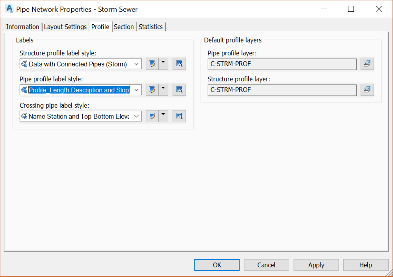
- On the Profile tab, we can specify the default label and layers to assign to the network parts in profile view.
- On the Section tab, we can set the default layers in the section view. Meanwhile, the Statics tab gives us a summary of all network parts.
- Click OK to close the Pipe Network Properties window.
- The next three items allow us to set the reference surface alignment and the part list to use.
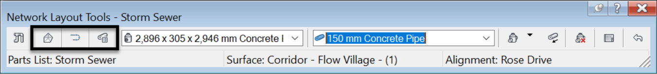
- Next, we can choose, depending on the part list we are using, the specific structure and pipe we are creating. Since we are creating catchbasins, let's go with a rectangular junction box. Let's also choose a default 300mm or 12in pipe.
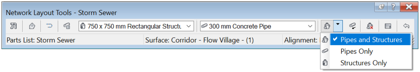
- Next, we can decide to create Pipes and Structures, Pipes Only or Structures Only. That depends on our current needs. In this case, we are creating more catch basins and leads, so we need both.

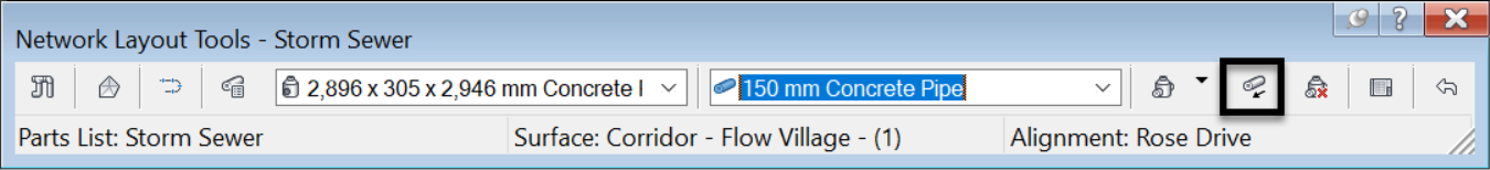
- The next command allows us to Toggle Upslope/Downslope. That means we can specify whether the slope of the pipe network is upward or downward, in order to apply the proper pipe rules.
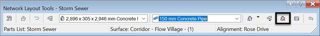
- The next command of the Pipes Layout Tools allows you to delete network parts. You can do the same in the drawing by simply selecting a set of parts and hitting delete on the keyboard.
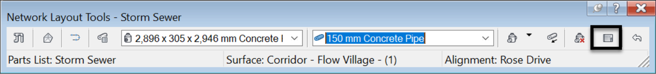
- Next, we have the familiar panorama vista of the Pipes Layout Tools , which gives us access to a tabular view of the network parts and data.
- On the left side of the vista, we have two important tabs that give us access to StructuresandPipes. We may also have a third one giving access to the Grading Editor if a feature line is currently in editing mode.

- Now that we have perused the layout tools let’s use them to create pipes and structures. Run the Pipes and Structures creation command.
- Click in the middle of the first catch basin circle. Make sure you have your circle object snap activated or use the CEN command line alias.
- Once you click, the catchbasin is added. Next, bring your cursor close to an adjacent manhole, then click once you notice the small yellow symbol. That means that your pipe is being connected to that structure.
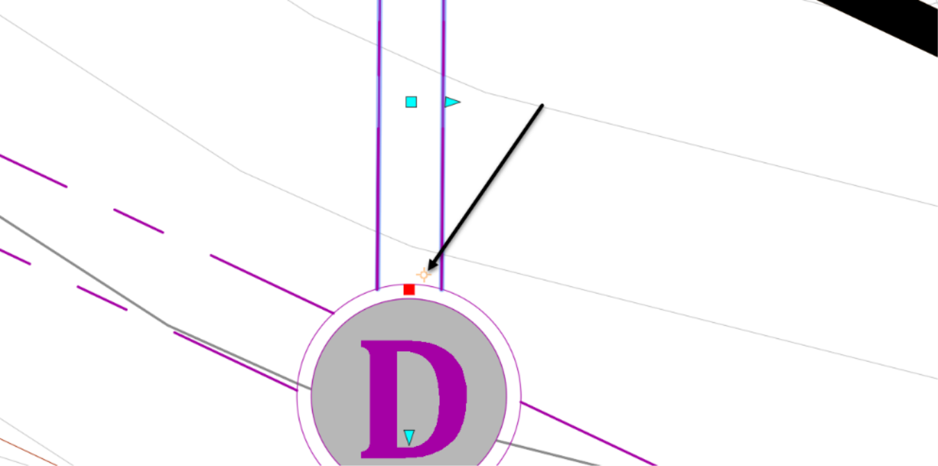
- The catchbasin and lead are now created and tied to the connection manhole.
