-
Get It
$19.99
$19.99Civil 3D Essentials Book and Practice Files
Civil 3D Profile and View Style: A step by step tutorial guide
Introduction to Civil 3D Profile Style and View Style
Firstly, what is are the Civil 3D Profile Style and View Style? Well, let's find out in this online training course. Certainly, this step by step tutorial is a part of the Civil 3D essentials book and how-to manuals.
Working with Civil 3D Profile Style?
The profile is the line representing the vertical alignment. The profile style is therefore different from the profile view style we just talked about.
To assign or modify the style of a profile,
- First, select the profile in the view.

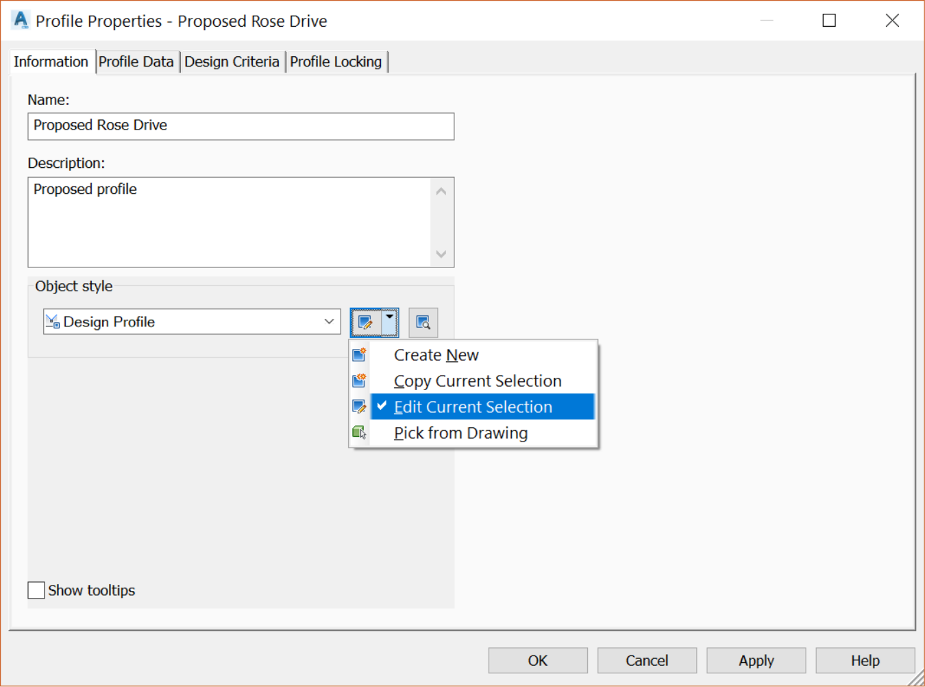
- Right-click and select the Profile Properties

- On the Information tab, in the object style section, we can apply or modify a pre-existing style, create a new one or apply a style from the drawing. Let's try to Edit the Current Selection.
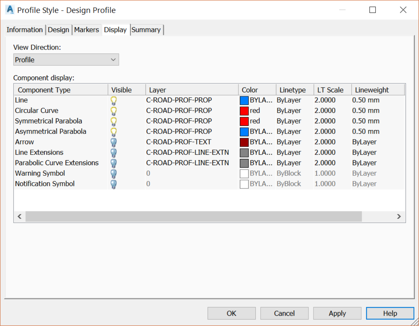
- On the Display tab, we can set the visibility and format of profile components, such as lines, curves, arrows, warning symbols, and all the others.
Working with Civil 3D Profile View Style?
To assign or edit the style of the profile view we need to:
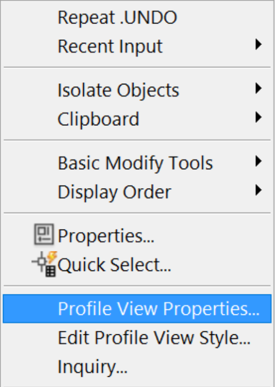
- First, select the profile view in the drawing.

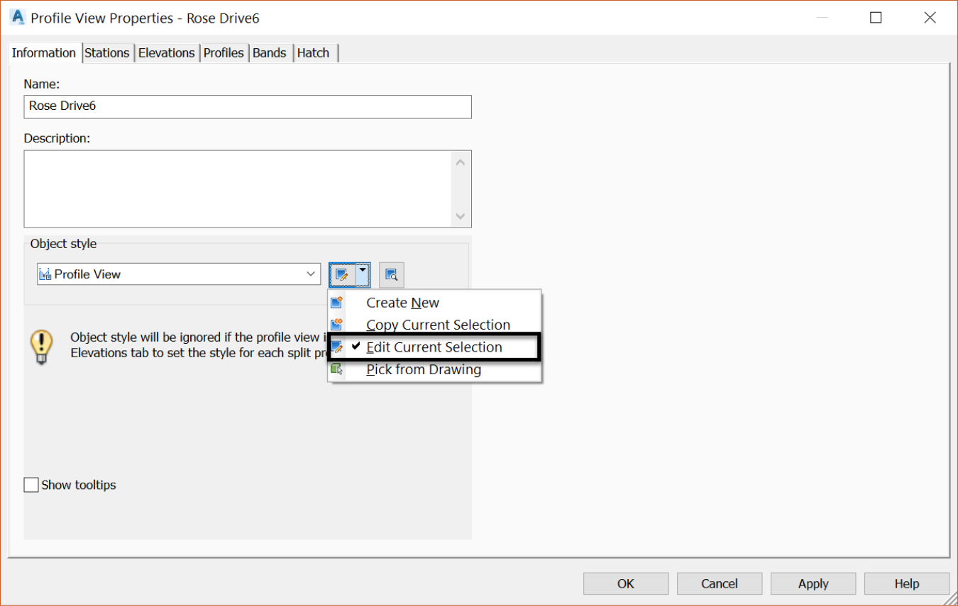
- Right-click and choose Profile View Properties.
- On the Information tab, we can either assign a pre-existing style, create a new one, or copy another style, then modify it to fit our needs.

- Let's choose to Edit the current selection and modify the current style.
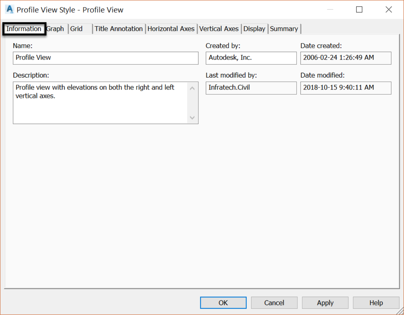
- The Profile style Editor opens, and we can make all needed modifications to display the profile view as we need.
- The first item is the Information tab. Here we can record basic information about the profile view style. That includes the name of the person who created the style, the date of creation and modification, etc.
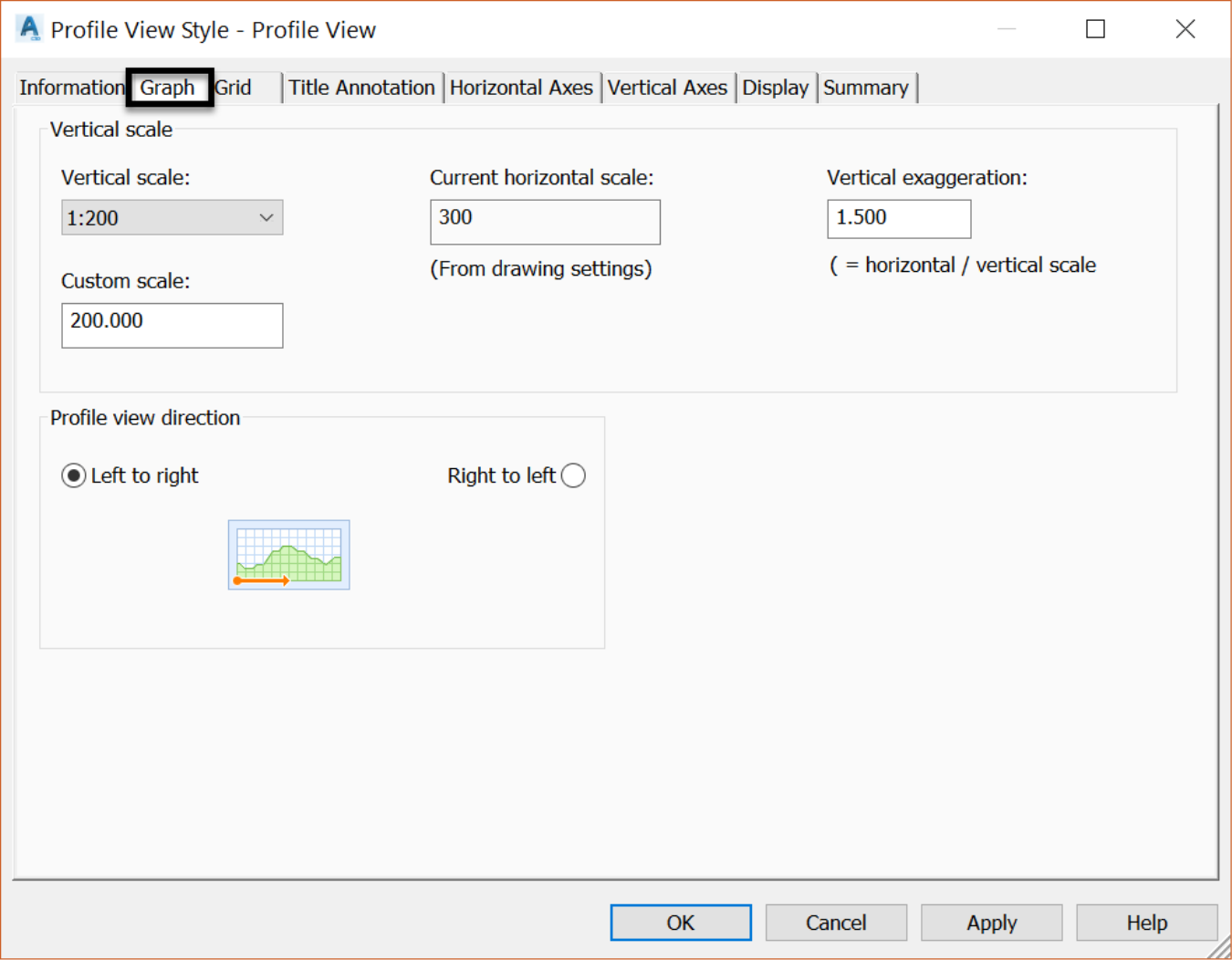
- Next is the Graph tab: you can use this tab to set the vertical scale and direction of the profile view. The vertical scale controls how much you want to increase the elevation to improve visibility in the profile view. This does not affect elevation data per se. It is strictly a visibility feature. This can be done either by vertical exaggeration or simply by entering a scale value. When one is used, the other is calculated automatically. Profiles are typically drawn from left to right, but situations may arise where you need to go from right to left.
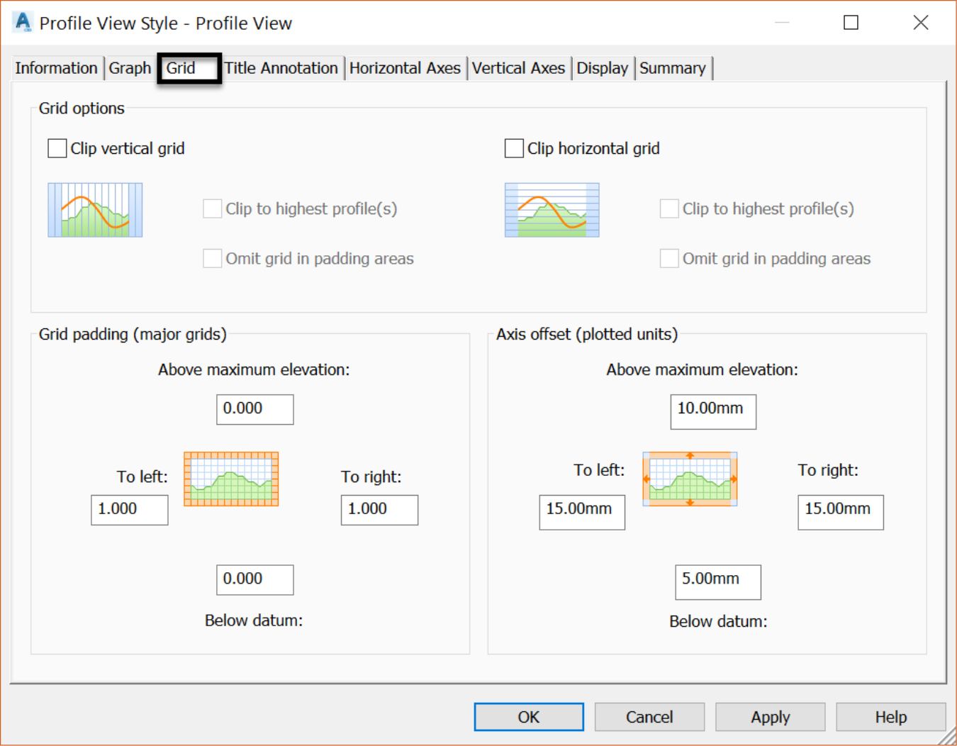
- The Grid tab mainly controls the clipping, padding, and axis offset options on the profile view grid.
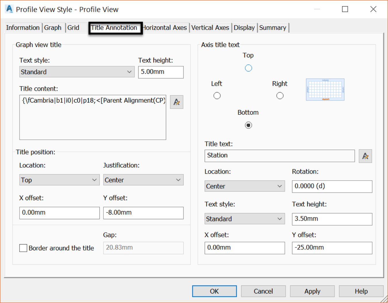
- The next tab is Title Annotation. Here we can specify settings for the graph view, including graph and axis titles with options. That includes text content, height, style, rotation, offset and border style.
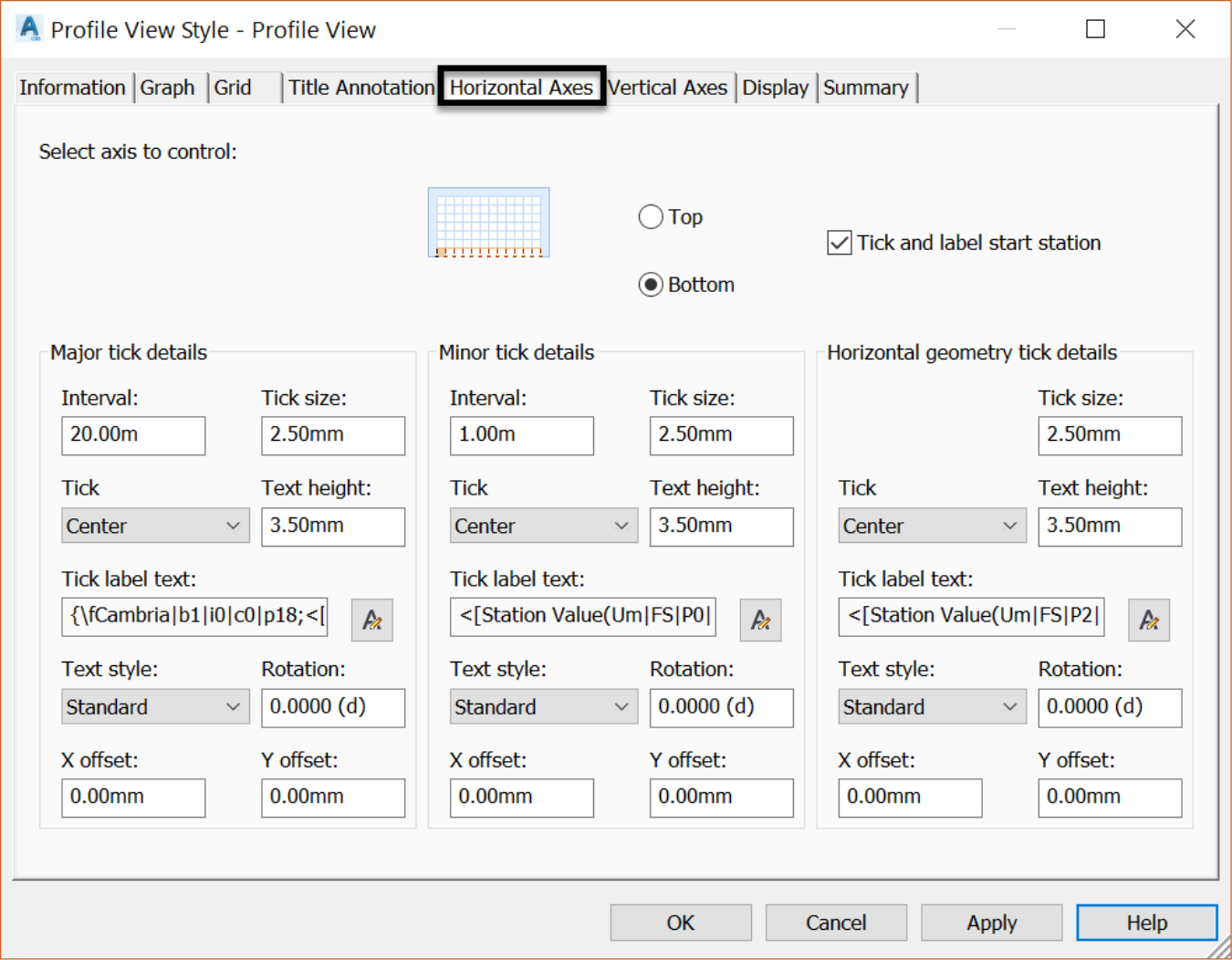
- Next, we have the Horizontal Axes tab. We can use it to specify the settings for the major and minor stations such as the text and tick marks on the horizontal axes of the profile view.
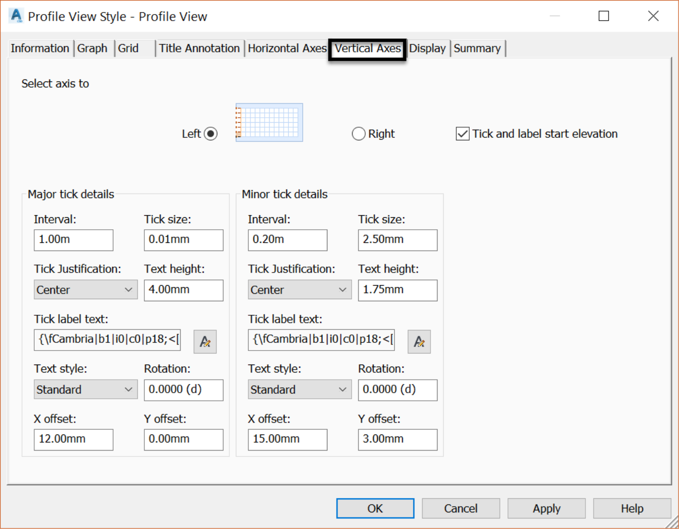
- The next tab is Vertical Axes, where we can specify the settings for the text and tick marks on the vertical axes of the profile view. We can pick the left or right vertical axis to adjust the Major and Minor elevation Details.
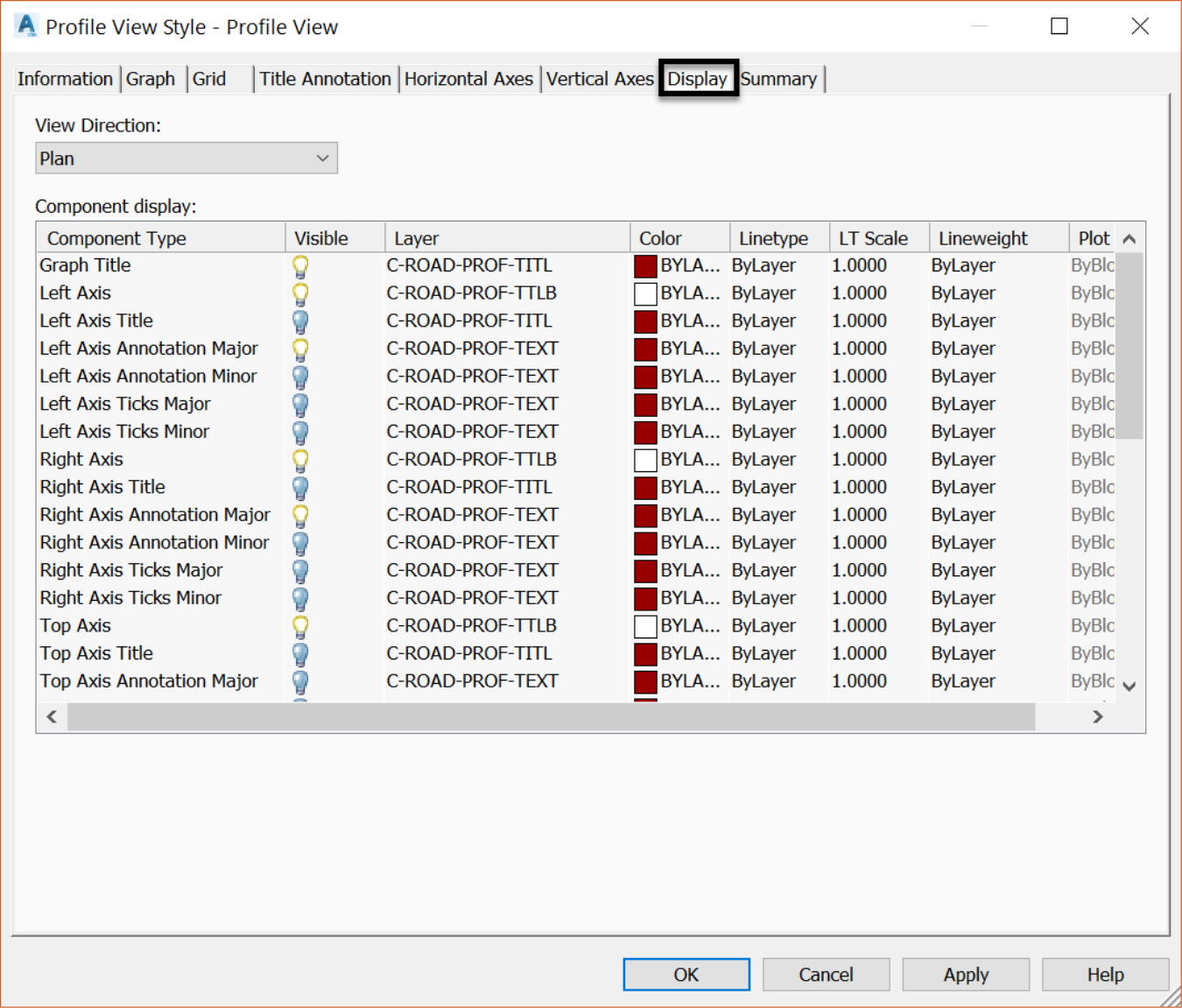
- Next to last is the Display tab where we can manage the display of profile view components in 2D and 3D. On this tab, we can turn on or off most of the settings that we saw in the last few tabs.
- Finally, we have the Summary tab where we can review and adjust all of the settings we have seen for the profile view style.