-
Get It
$19.99
$19.99Civil 3D Essentials Book and Practice Files
Civil 3D Proposed Profile (Layout Profile): A step by step tutorial guide
Introduction to Civil 3D Proposed Profile (Layout Profile)
Firstly, what is a Civil 3D Proposed Profile (Layout Profile)? Well, let's find out in this online training course. Certainly, this step by step tutorial is a part of the Civil 3D essentials book and how-to manuals.
Working with Civil 3D Proposed Profile (Layout Profile)?
The next step is to create the design of the road. Unlike a Surface profile, which represents a pre-existing surface, the proposed profile must be designed. This is done according to established standards. This includes horizontal and vertical geometry design for safe driving conditions.
Minimum requirements for roadway design are usually spelled out in design manuals. They are typically published by the federal transportation authority. Sometimes, a stricter version of the requirements is enforced at the local level. Among such requirements are speed limits, safe driving sight, and the like.
To create the design profile (also called proposed profile), we need to proceed as follows:
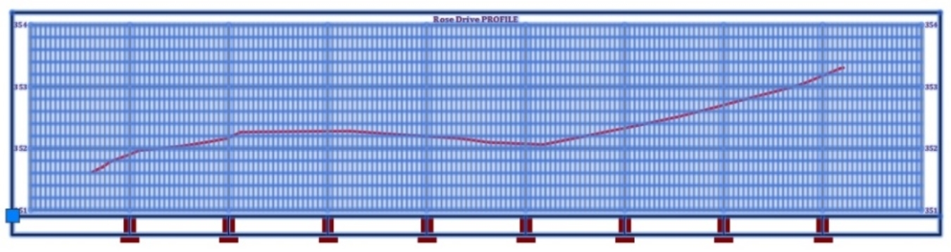
- First, select the Rose Drive profile view we have just created.
- Then, from the Ribbon, launch the Profile Creation tools.

-
Afterward, enter the profile creation settings in the Create Profile dialog box. In particular, let’s specify,
- The Name of the profile
- The Profile Style
- and the Label Set to use.
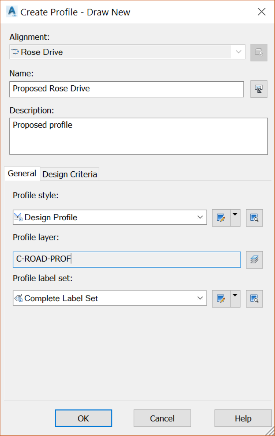
-
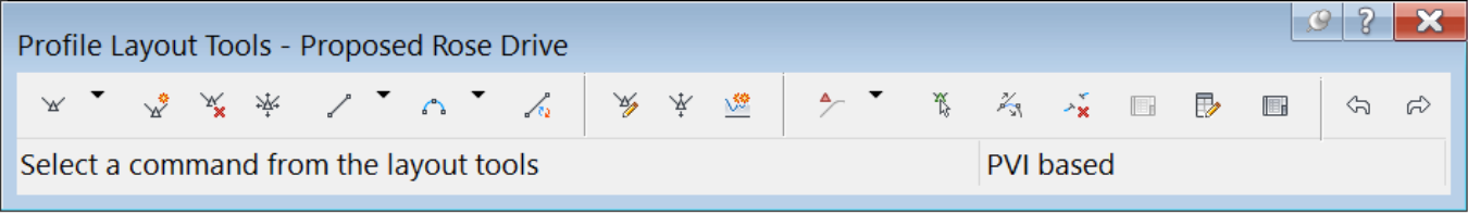
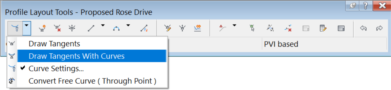
Click OK,and the Profile Creation Tools will appear on the screen. If it looks familiar, it is because we have just used something similar, the Alignment Creation Tools, which has analogous commands.
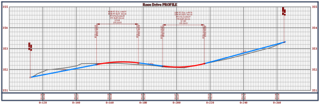
Now, let's set curves and tangents design parameters.
- In the Vertical Curve Settings dialog box, use 25m or 75ft for Crest and Sag Vertical Curves. Alternatively, we can use the K value, which is mathematically linked to the curve length.

- Now let's create tangents and curves for the proposed profile.
- Click the start point of the existing ground profile. Make sure you have your End object snap option activated or simply type the alias end at the command line. We are clicking on the existing ground because we are trying to match the existing ground at the tie-in point. Ideally, we would like to have the road grade at that location so that we can carry it out a few tens of meters or feet before any change of slope. For now, let's assume that the slope that we are creating is the same on the other side of the project.
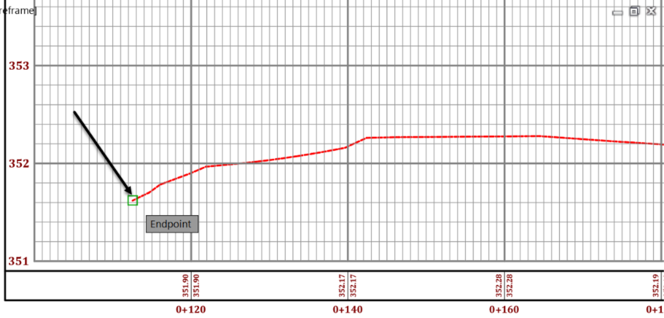
- Next, click on a few points (4 or 5) along with the existing ground profile. During this process, try to minimize cut and fill volumes, meaning we don't want to be too high or too low compared to the existing ground. We want to have something like this.