-
Get It
$19.99
$19.99Civil 3D Essentials Book and Practice Files
Civil 3D sample lines : A step by step tutorial guide
Introduction to Civil 3D sample lines
Firstly, what is a Civil 3D sample line? Well, let's find out in this online training course. Certainly, this step by step tutorial is a part of the Civil 3D essentials book and how-to manuals.
Working with Civil 3D
Cross-sections enable us to examine existing and proposed surface elevations. In Civil 3D, section data is defined and displayed using sample lines grouped in a collection called a sample line group.
The Civil 3d sample line creation wizard allows us to create cross-sections. We can create them at given intervals, and at a specified left and right distance from the alignment centerline.
In this project, we will create cross-sections at 20m or 50ft intervals along Rose Drive. To do this, we need to create sample lines that will represent the stations where the sections will be cut.
- Open the 11.01-Sections dwg file in the Lesson 11 practice folder. You will notice that we did a little more work in the drawing from where we left in the last lesson. In particular, we created the sanitary and water network. We have also projected these two networks in their respective profiles and added labels in plan and profile views.
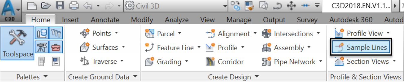
- To create sample lines, launch the Sample Lines creation command.
- When prompted to select an alignment to create sample lines for, press Enter at the command line. Note that you can directly click on the alignment in the drawing to select it. However, clicking in the drawing is not recommended when you have a huge number of overlapping alignments. We could potentially click on the wrong alignment.
![]()
- In the Select Alignment window, select Rose Drive and click OK.

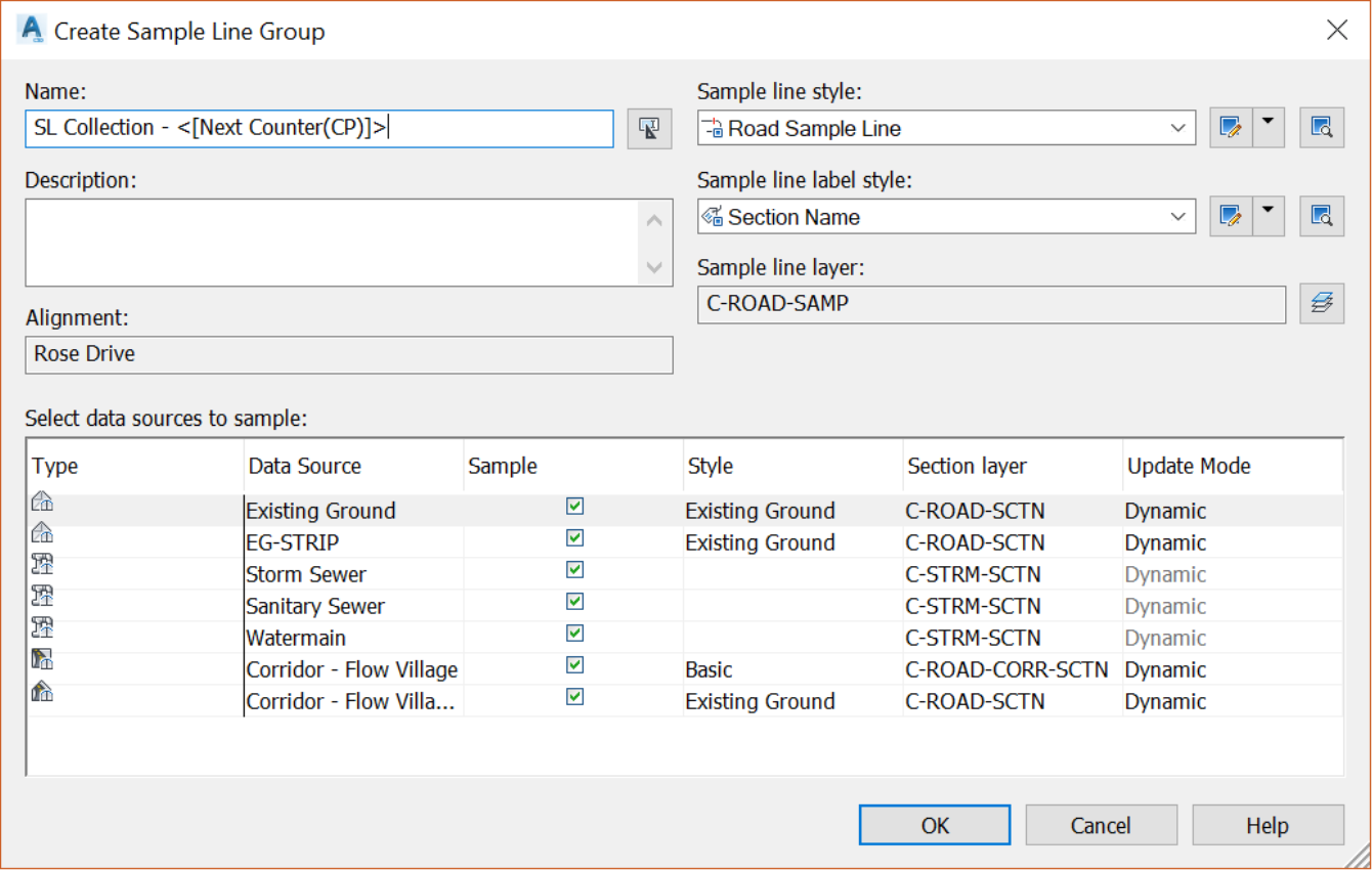
- In the new Create Sample Line Group dialog box, select a Civil 3D object that can be sampled, such as surfaces, corridors, and pipe networks. In the current situation, we will choose all existing surfaces and the corridor. In this same window, we can specify the sample line styles, as well as the layer. Let’s leave all the options to the default ones and click on OK.
- Next, we are presented with the Sample Line Tools that will enable us to create sample lines according to our specifications. It’s not the most obvious thing to notice. But, the sample line creation method and the working alignment are displayed at the bottom of the toolbar. In this case, we can see that the current method is By Station.

- Let’s go ahead and provide more details for the sample lines creation. On the Sample Line Tools, create new sample lines By range of stations.

- Then, in the Create Sample Lines–By Station Range window, we will proceed as follows:
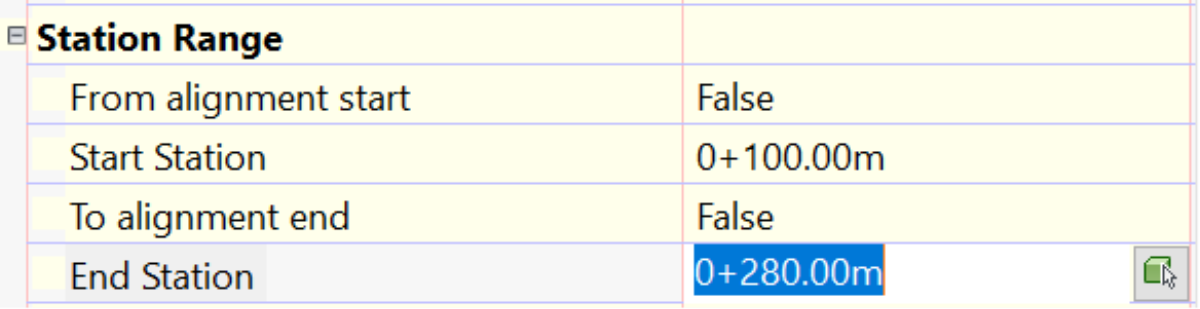
- First, set From Alignment Start and From Alignment End values to false. This means that we don’t want to create sample lines, thus sections, on the entire length of the alignment. Therefore, we need to specify where we want to start and end. Click inside the text box to the right of Start Station. To the right of the -0+000.00, click on the small green cube and white arrow icon
 . Next in the drawing, click on Rose Drive, just before the start of our project, on the west end. Maybe, at station 0+100m or 0+320ft. Alternatively, if you know the exact station where you want your sections to start, you can just type in the station values.

- Our start is now set.

- Repeat the same process to set the End Station. This time, to specify the station, click on the alignment, just before the roundabout at the east end, something like station 0+280.00m or 0+920.00ft.
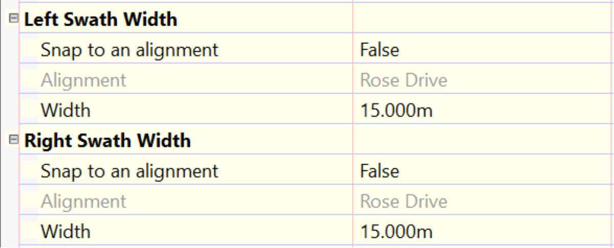
- Next, we need to specify the Swath Widths. This means how far left or right of the alignment centerline we want to sample. We want to cover the entire right of way and maybe a few meters or feet inside the lots. So 15m or 50ft on both sides will be more than enough. Note that we have an option to Snap to an alignment for the definition of the swath width. This option extends the sample lines out to an alignment, an offset alignment for instance, rather than a fixed width. This scenario does not apply to us, so we will simply choose False on both accounts.
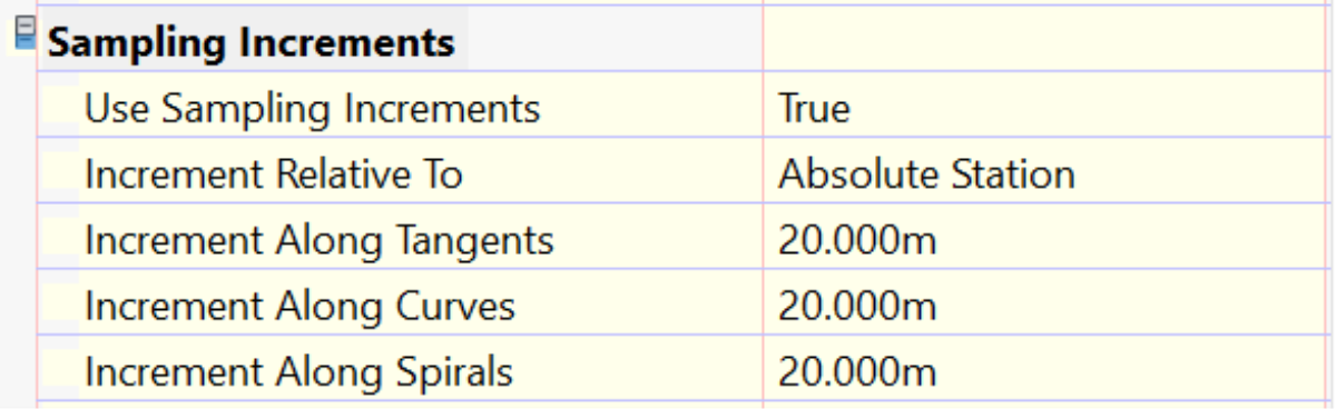
- Next is another important item on the list, the Sampling Increments. To use regular increment values, we need to set the Use Sampling Increments line value to True. We will enter 20m or 50ft along both tangents and curves. We don’t need to worry about spirals since we don’t have any on this street.
- Finally, we need to set some Additional Sample Controls, to create, or not, more sample lines at specific locations along the alignment. Let’s go ahead and answer True for At Range Start and At Range End. This is specifically important when calculating material quantities. They are, most of the time, computed using the average area method between two sample line stations. This is so that you don’t miss quantities by not creating sample lines at the start and end of the project.
- Once you are done with the Create Sample Lines window, click OK to create the lines.
- When requested to choose additional locations to create sample lines at the command line, hit Enter or Escape.

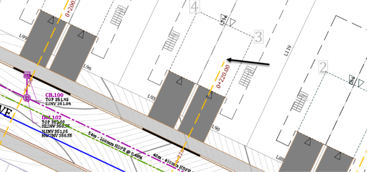
- Observe the sample lines created at each major station every 20m or 50ft.

Checking sampled sources
Before creating the sections, you may need to check if all the surfaces have been properly sampled. Remember that, if a surface is created after the sample lines, the surface will not be included in the set of samples. So, we need to make the Sample Lines Group aware of newly available sources. To do that,
- First, right-click on one of the sample lines.
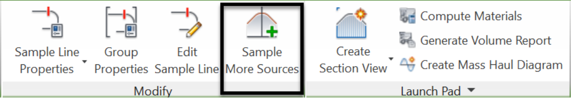
- Select Sample Additional Sources from the ribbon.
- If prompted to, click on one of the sample lines again.
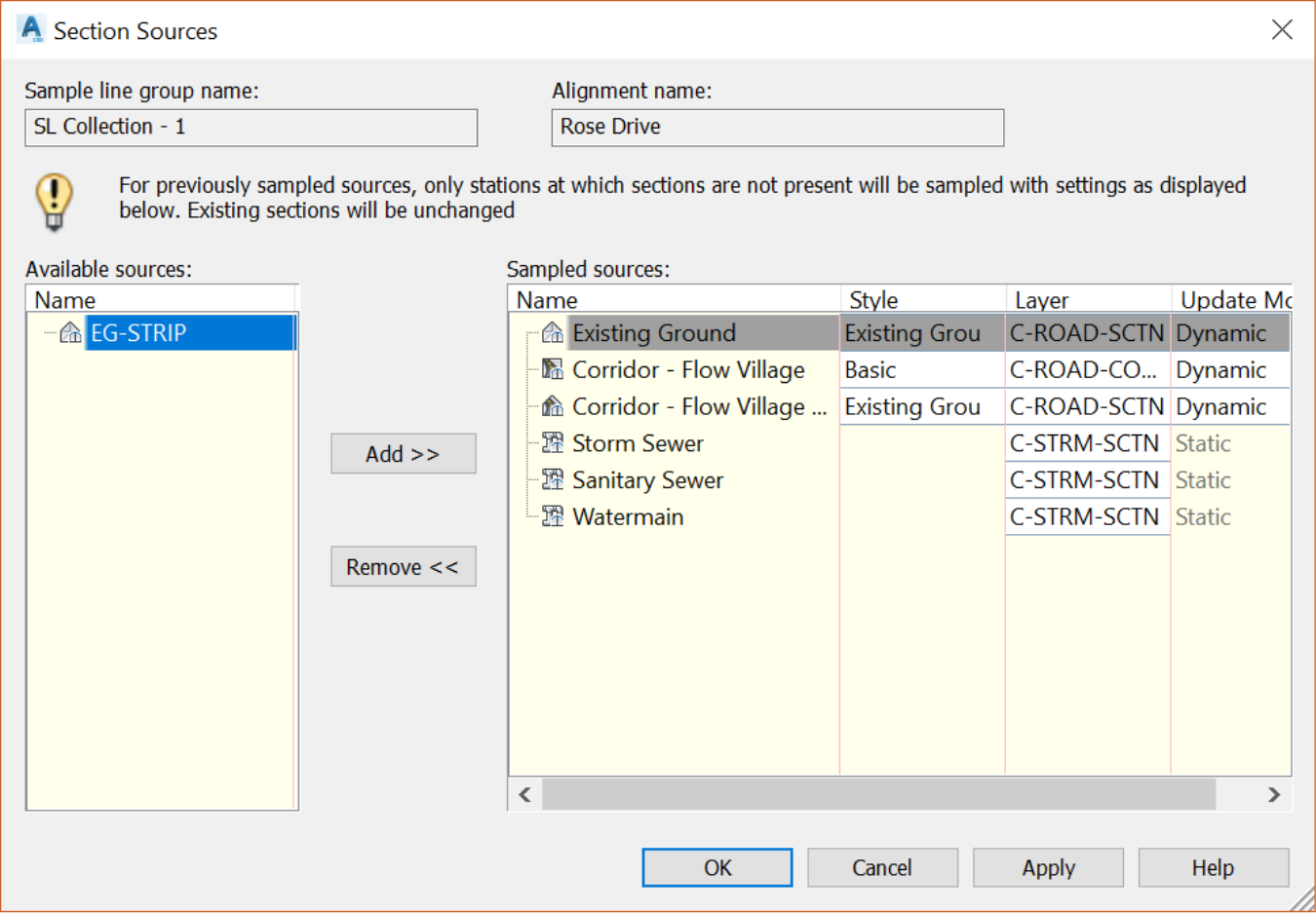
- In the Section Sources, on the left side, there’s a section called Available sources. On the right side, we have a list of already sampled sources. If we had created any new source, surface or pipe network, after the sample lines, they would be shown in the left section. In our case, we have sampled all the sources. On the other hand, maybe we don’t want to use certain sources in the sections. Case in point, we don’t need to show the EG-STRIP surface. To remove it from the sampled list, select it and click on the Remove button.
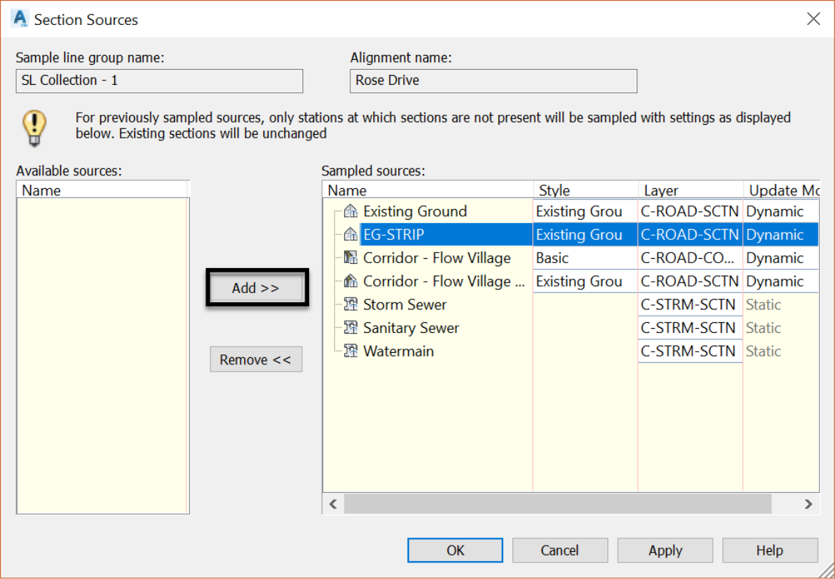
- The EG-STRIP is now removed from the list.
- Click OK to exit the Section Sources window.