-
Get It
$19.99
$19.99Civil 3D Essentials Book and Practice Files
Civil 3D Section View Bands: A step by step tutorial guide
Introduction to Civil 3D Section View Bands
Firstly, what is a Civil 3D Section View Bands? Well, let's find out in this online training course. Certainly, this step by step tutorial is a part of the Civil 3D essentials book and how-to manuals.
Working with Civil 3D Section View Bands
It would be convenient to show some information along the sections. That’s where Bands come in. Most of the time, we attach them as tables associated with each section. We can use them to display design information, including profile elevations, cut and fill data, pipe networks, and much more.
- Let's add some bands to show the elevation information for the proposed and existing surface along with cut and fill depths. To do that,
- Select a cross-section view,
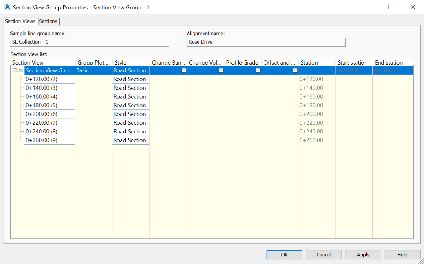
- Right click on Section View Group Properties.

- The Section View Group Properties window is the main place where you edit section view settings and styles. Here, you can create or modify Group plot styles, band sets, profile styles, view offsets, elevations, and sections styles. For example, let’s see how to work with bands. Let’s click on Change Band Set.

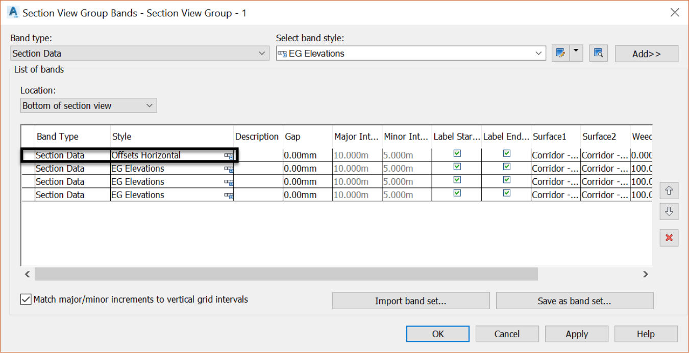
- Click on Add
 three times to add bands. We will have four in total, one for the stations, one for the existing ground, another one for the proposed ground and the last one for cut and fill depths.

- In the Gap column, change values to zero for all bands, except the offset horizontal. We will set it at 15mm or 0.6in, to put it below the section border margin.

- Click OK twice to preview the bands. You will notice that more adjustments are needed to the bands. To do that, we have several options such as changing text sizes, widths or heights of the bands, or increasing the spacing between sections.
- Let's start by adjusting the width of the bands. Return to the Section View Group Properties window.
- Open the Change Band Set page.
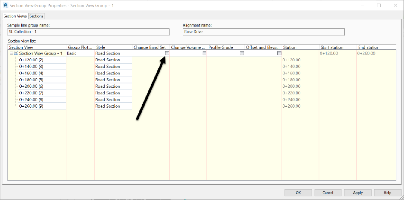
- To adjust the widths and heights of a band, for example, the Offsets Horizontal one, click on the small band style symbol to its right
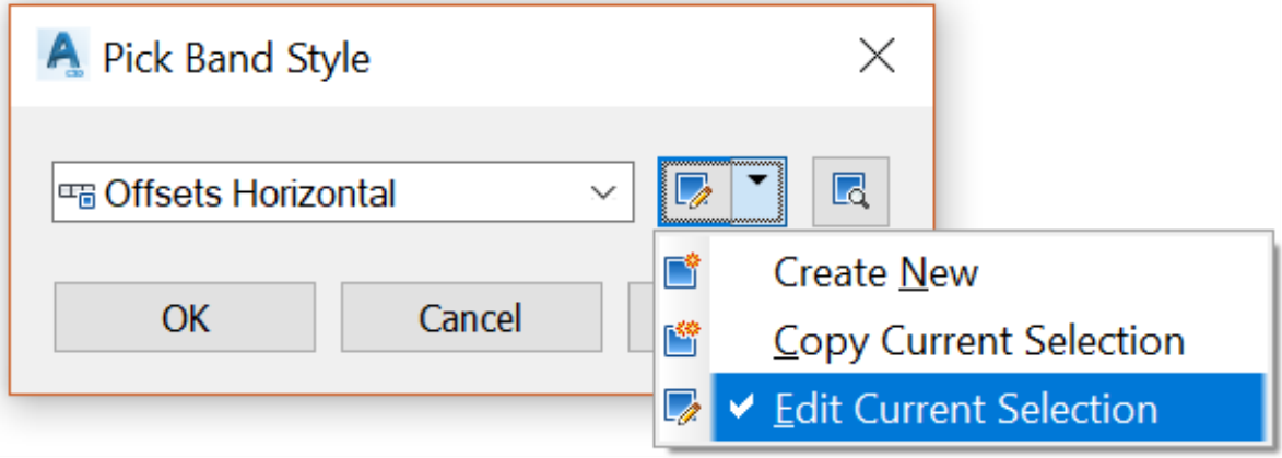
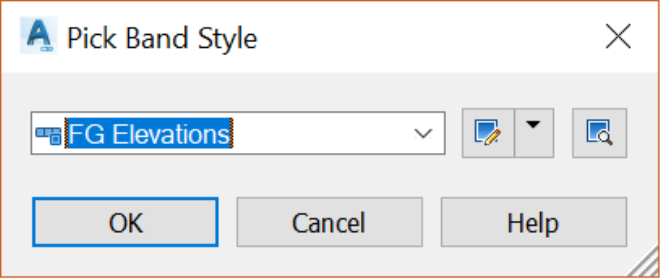
 and edit it in the Pick Band Style dialog box.
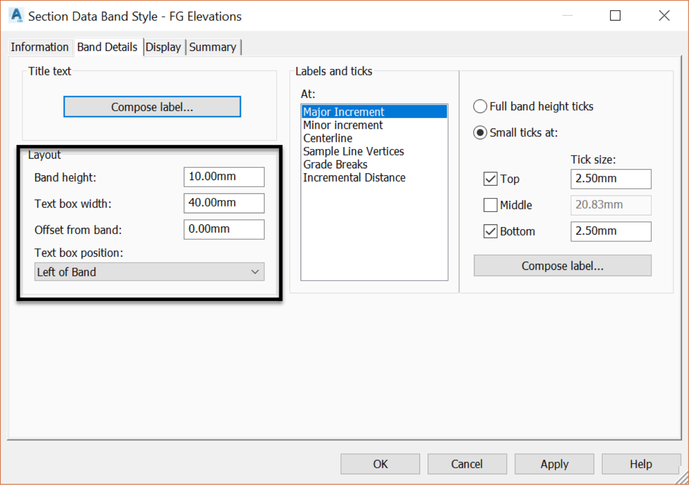
- On the Band Details tab, in the Layout section, assign
a height of 10mm or 0.4in,
a text box width of 40mm or 1.6in and
a 0 for offset from band.
- The first band style is already set to Offsets Horizontal. So, we will leave that one as-is. It will represent the station values of the section view.
- Next, change the EG Elevations style to FG Elevations by clicking on the small band style symbol to its right
 .
.

- Then pick the FGElevations Style in the Pick Band Style dialog box.
- On the third line, we are already set with the EG Elevations styles, which we will use for the existing.
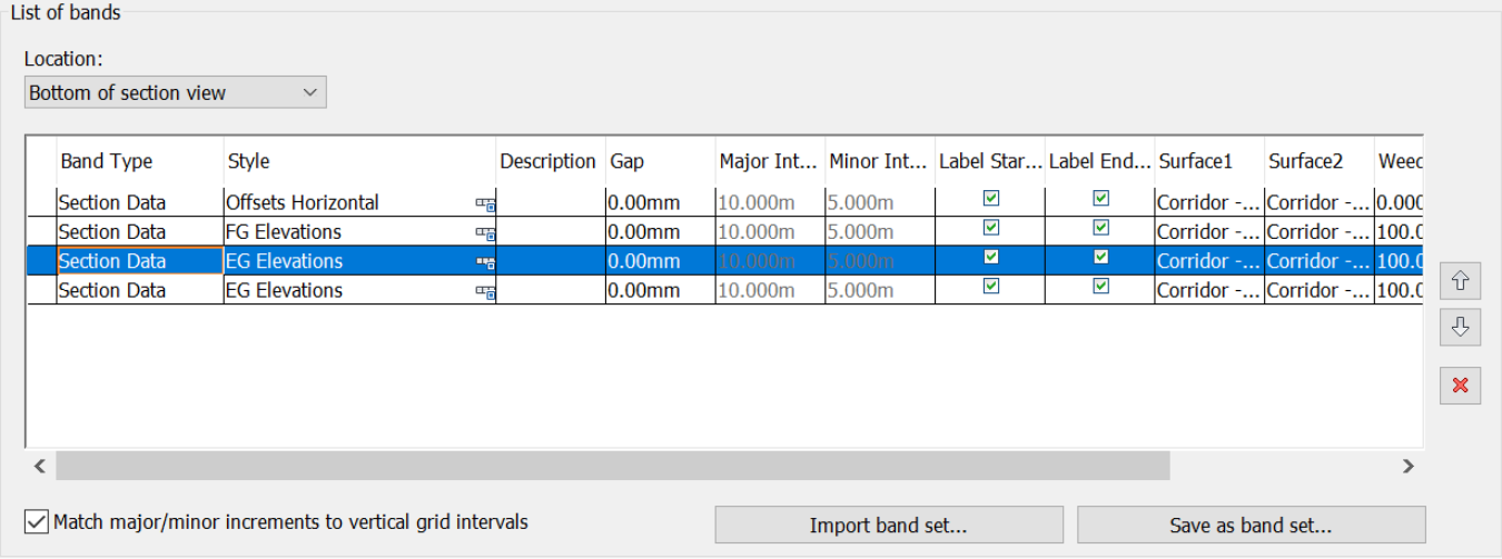
- On the last line, select the Cut or Fill band style.
- Click OK on all the windows and observe the changes. We already see an improvement in the bands.

- However, we still need to populate the band with elevation information at the major stations. Also, line styles could also use some improvements. To populate the elevation data, we simply need to assign surfaces to the different brands, so they know which elevation to display. We also need to verify the weeding factor. Sometimes, it prevents data to be displayed. A quick note that the weeding option is used when we don’t want to display the information at intervals too close. So, if we choose a weeding of 20m or 75ft, for example, the labels will be shown at a minimum every 20m or 75ft. All labels between this interval will be weeded out.
- Return to the Section View Group Properties and open the Bands window.

- As expected, we need to assign the proper surfaces and also change the weeding from the default values to zero. Make sure all surfaces in the Surface1 column are set the Corridor Surface, and the ones in the Surface2 column are set to the Existing Ground surface.

- Click OK to close the Section View Groups Bands window. The bands are now filled with data, at all offsets, where we have an existing or proposed ground elevation.
- Now let’s go a little deeper in the band's rabbit hole and explore where they are set up to display the information they show. Return the Section View Groups Properties window and from there, open the Section View Group Bands window. Let’s edit the FG Elevationsstyle by clicking on the symbol to its right and edit the style.
- On the Information tab, we have the usual style records.
- The Band Details tab is where most of the setup is done. The Title text section is where we set up the band title, the information that is displayed to the left of the band data. In this case, we have Offsets, FG Elevations, EG elevations, and so forth. To change it, simply click on Compose label; and change the content in the Label Style Composer.
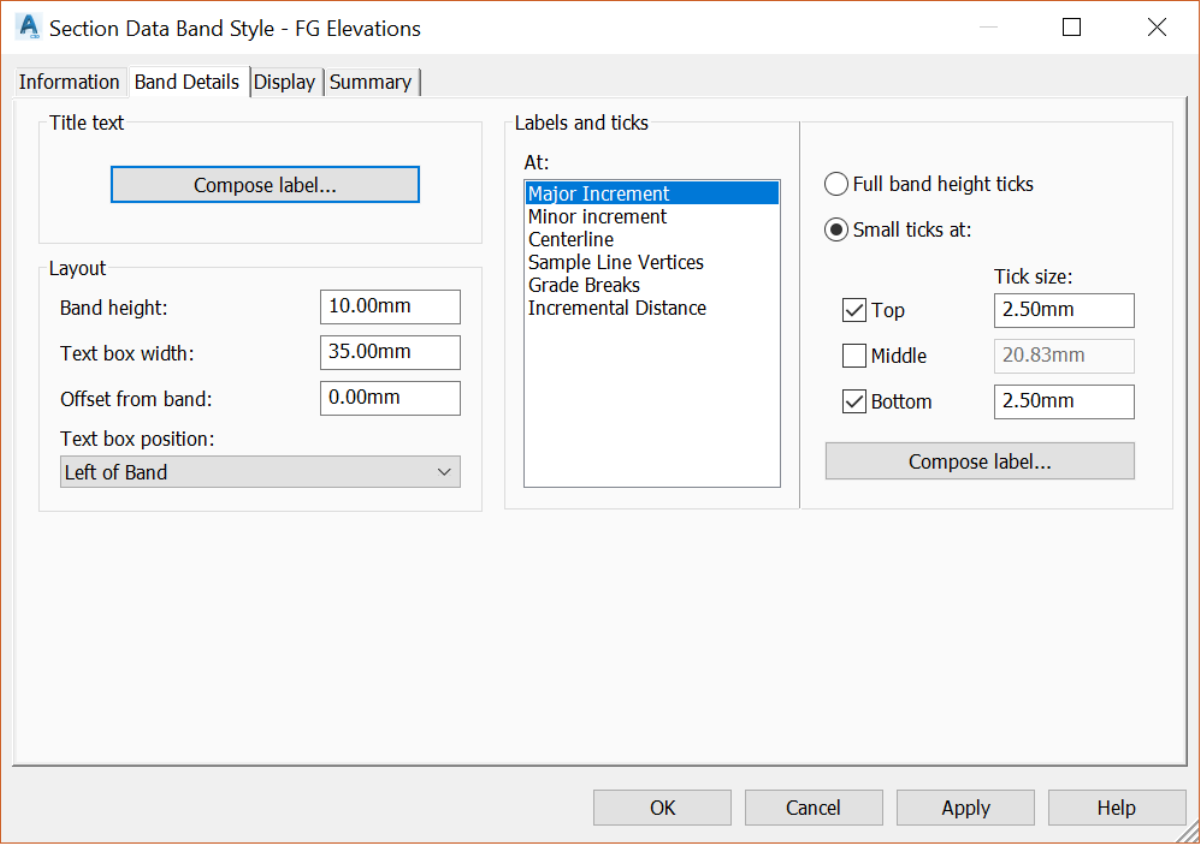
- The Label and ticks area is where we decide the data to display, at specific locations. That can be Major and Minor stations or increments, centerline, sample line vertices, grade breaks, and incremental distances. Our labels are displayed at major stations. So, let’s select Major Increment and click on Compose label to set the label content.
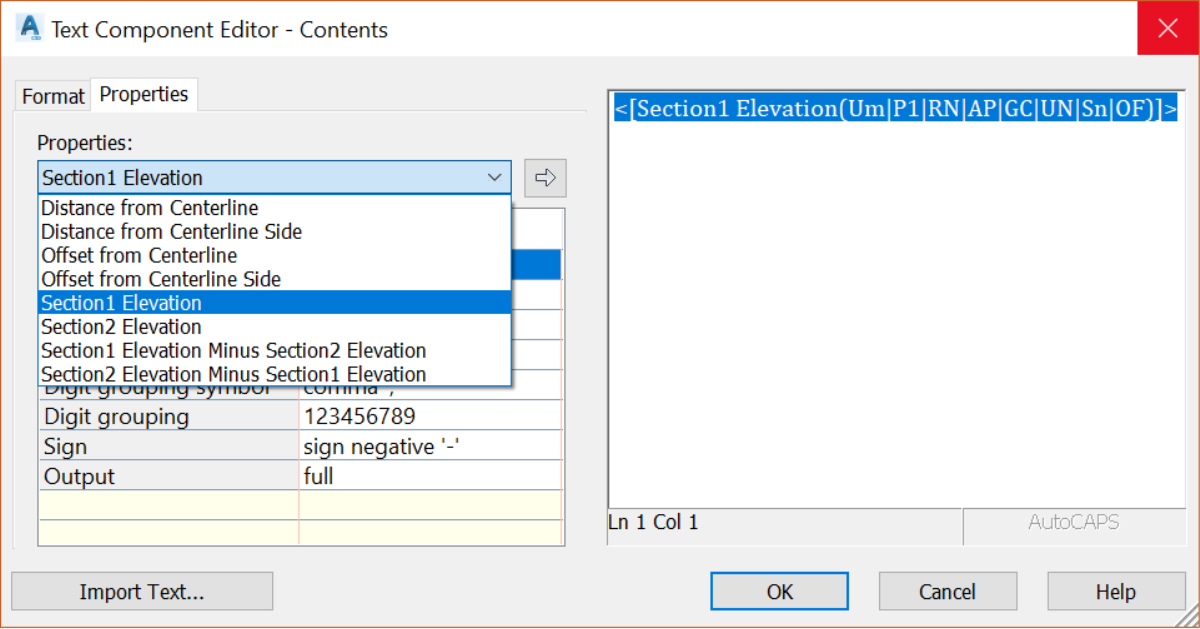
- In the label style composer window, the most important line is the Contents. So, click on there to edit the content of the label. In the Text Composer Editor window, we can choose different properties to display, including distances, offsets, Section 1 (our proposed ground) or Section 2 (the existing ground) and elevations. We can even estimate cut and fill by choosing to display the difference between Sections 1 and 2.
- Click OK twice to return to the Section Data Band Style window. On the Display tab, we can edit the visibility and format settings for the section view component styles, including borders, titles, and labels.
- Click OK four times to close all the windows.