-
Get It
$19.99
$19.99Civil 3D Essentials Book and Practice Files
Civil 3D Surface Label and Table Styles: A step by step tutorial guide
Introduction to Civil 3D Surface Label and Table Styles
Firstly, what is a Civil 3D Surface Label and Table Styles? Well, let's find out in this online training course. Certainly, this step by step tutorial is a part of the Civil 3D essentials book and how-to manuals.
Working with Civil 3D Surface Label and Table Styles?
As we've seen in the lesson on Points, most Civil 3D entities have two types of styles: the object style and the label style. The first controls the "look" of the object itself, while the latter controls the annotation that goes with the entity. For example, a surface will need spot elevation, contour elevations, and slope values. While an alignment would need stations and offsets, and manholes would need Rim and pipe invert elevations. These are all called Civil 3D labels, and the way they are displayed constitute the Label Style.
Practicing with Civil 3D Surface Label and Table Styles?
Let's create a couple of Civil 3D Surface Label and Table Styles: slopes and spot elevations styles. To make it easier to create labels, use the global label creation dialog box.
On the ribbon,
- Click on the Annotate tab, then to the far left, click on Add Labels. When you hover over, there are two sections, the Top and Bottom part. You need to be careful on which one you click, as they will lead you to two different paths. You may still be able to find your way and add Civil 3D Surface Label and Table Styles, but the process will be different. We want to click on the top part.

- That brings up the Add Label dialog box. This is a global window for labels, as it is common to most objects. Options available in the dialog box change depending on the selected feature. If we choose to label a surface, the type of Civil 3D Surface Label and Table Styles we will be able to create will be different than those for say alignment or profiles.

- Change the feature to Surface. For label type, choose Spot Elevation. We already have a few labels styles that come with our default template like EL: 100.00, which display elevations in that format. Now, suppose that we want to create an elevation style that will display information on two surfaces, at tie-in locations like the back of lots. At these locations, we want to display the proposed elevation and the existing ground elevation. We don't currently have a Civil 3D Surface Label or Table Styles that can do that. So, we will have to create one.
- On the information tab enter the name of the label, say Spot Elevation - EG and PR and the description, existing and proposed elevation for example.
- On the General tab, we can specify things like label visibility, label orientation, layer, and the like.
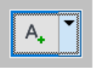
- The Layout tab is where most of the Civil 3D Surface Label and Table Styles creation action takes place. This is where we create the label components and control visibility. The components already created are displayed in the Component Name box. We can create new components such as text, lines, blocks, etc. by clicking on the A+
 symbol to the right.
 - First, let's change the name of the default text component from Surface Elevation to FG – Elev. This will make it clear that this component provides elevations for the FG – Finished Ground. We can also change the text size for the label, and other properties.
- Let's also change the Surface Elevation component name to FG – Elev, to make it clear that this component is for FG or Finished Ground. In this window, we can also change elements of the label like text styles and height, rotations, colors, lineweight, border, and more.
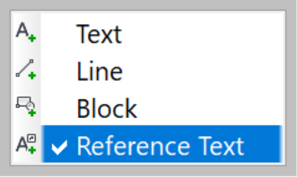
- For our second surface elevation, we need to add a second text, besides the default, Surface Elevation text component that we just edited. The type of text we will need this time is not the first type that says Text but the last one, Reference Text. The difference is that using Text will give us information on the current surface we are attaching the label to, the proposed design surface. While the Reference Text will reference another surface, the existing ground surface.
- So, click on the reference text.
- Our surface label style will be able to grab information from different types of entities such as alignments, profiles, parcels, and the like. This capability has several great applications in creating all types of labels. In the Select Type window, choose Surface. That's because, besides our proposed surface, we also want the label a reference elevation from the existing ground.
- Click OK.
- A new text component is created with the name: Reference Text.1.
- Next, change the name of the newly created component from Reference Text.1 to EG – Elev to make its function more explicit. Giving obvious names is crucial. It facilitates managing styles and providing better template readability for future users of the file.
- When you open the Component Name box, you should have two components. If you have more than two, you can always click on the red X to the right
 to delete unwanted ones.
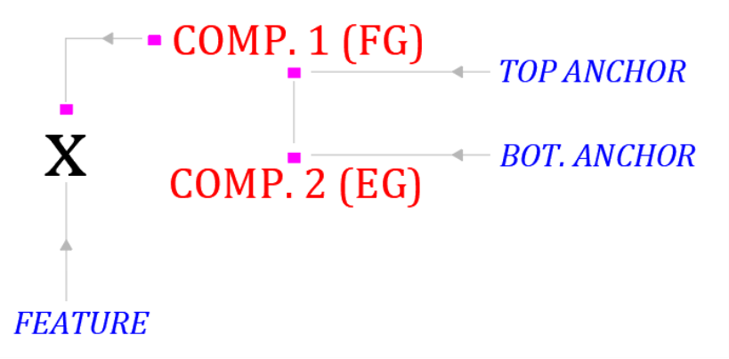
- One important thing, we need to understand is how to stack the different components we are creating. For good readability, we have different options to anchor the components in relation to each other.
- First is the Anchor Component, which means the object to which we want to tie the label. We can choose Feature to specify that we want to tie the component to the feature, meaning the point where we are creating the label style.
-
Once we specify the Anchor Component, we also need to determine the Anchor Point. It means in relation to the Anchor Component where do we want the label to be (left, right or middle)? For this label, let's decide to
- Anchor FG – Elev to the Top Right of the Feature, mean the point where we are putting the label
- Then we will anchor EG – Elev to the bottom of FG – Elev.To do that we can anchor the component FG – Elev to Feature.
- Next, we need to position the EG – Elev component. We can also anchor it to Feature. But we don't want it to overlap FG – Elev. So, instead, we are going to anchor it to FG – Elev.

- To summarize, so far, the proposed label component (FG) is anchored to Feature or the insertion point of the Surface label style, while the existing label component (EG) is anchored to the proposed label.
- Don't forget that you have a preview window that allows you to see how your labels stack while you are still creating them.
- Notice the question marks in the preview? That is because the EG – Elev references an external surface, which we have not specified yet.
Now that we have positioned the label the way we want let's work on the content, the actual information we want to convey with these labels.
- Start with the EG – Elev component. The proposed label is probably already set. To change the content, on the Contents line, when you click on the Label Text cell, you will notice an icon with three small dots. Click on it. We are familiar with this window. We have used it before in the template and styles lesson. Now first select Label Text in the editor, then the Properties drop-down box, select Surface and click on the horizontal arrow to apply that label.
- Once we do that, the reference surface elevation code will be applied. We also have an option to format the label display such as the label units (meter or feet), precision (decimal places), and others.
- One more thing, we will have two labels stacked on top of each other. So, we need to be able to differentiate them. Let's add a text in front of each, so we know what surface elevation they represent. In front of the elevation code, enter the surface name or initials, like EG.
- Click OK to return to the Label Composer window. Now select the FG – Elev component and do the same thing. First, go to the content line, click the content editor icon
 , then add the prefix FG before the elevation code.
- Click on OK twice to close the Text Component Editor and the Label Composer window to return to the Add label window. If it's closed, you can reopen it from the Annotate tab.
- Make sure our new style Spot Elevation – FG and EG is active and select Basic X style.
- Click on Add. At the command line, you are prompted to select a surface to annotate. You are presented with two options. You can either click on the surface in the drawing, if you can identify it. Or, you can press enter at the command line.

- Press enter at the command line. Ideally, at this step, we would pick the FG (Finished Ground) surface. Since we are not that far in the design, we don't have one yet. So, for the time being, let's select the Prelim-EG surface, just to simulate what would happen once we get our FG surface.
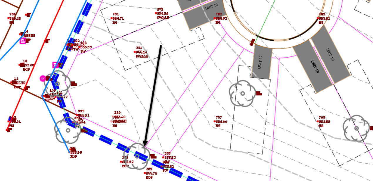
- You are now prompted for the location of the label. Let's choose the back of the lot for one of the parcels in the Lavender Courtcul-de-sac , to the west of the utility easement.
- Now that we have placed the FG label, we are prompted to select the surface that we are trying to reference for EG label.

- Press Enter at the command line to select Existing Ground for reference surface and click OK.
- We are then prompted to select another point to label. Let's just click on one more point and end the command.
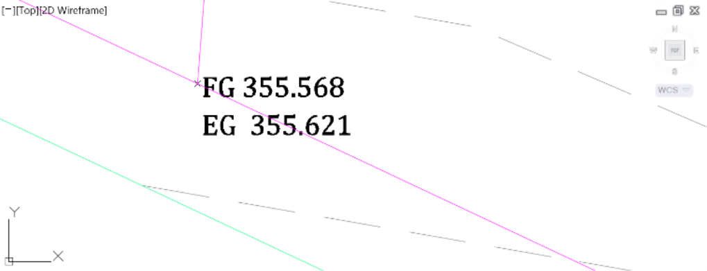
- We now have exactly what we wanted, a label style that displays both EG and FG elevations.
- You can press escape at the command line to end this command.
We will see later, how to add other types of labels like slopes and contours after we are done designing the Finished Ground.