-
Get It
$19.99
$19.99Civil 3D Essentials Book and Practice Files
Civil 3D Surface Profiles: A step by step tutorial guide
Introduction to Civil 3D Surface Profiles
create profiles from surfaceFirstly, what are Civil 3D Surface Profiles? Well, let's find out in this online training course. Certainly, this step by step tutorial is a part of the Civil 3D essentials book and how-to manuals.
About Civil 3D Profiles?
In the previous lesson, we have learned how to create alignments. They give us 2D information along a path. Profiles are the tools that give us the third dimension or elevation along the alignment. For this reason, profiles are often called vertical alignments. Whereas the alignment itself is called horizontal alignment.
Therefore, a profile must always be associated with alignment.
In general, we will have two main types of profiles: a surface profile, created from a pre-existing surface and a proposed or layout profile. Both profiles can be superimposed in a common view. This gives us an overall view of existing and proposed conditions. Surface profiles can be dynamic (with automatic updates that reflect changes made to the associated surface). In some rare circumstances, we may also choose to make them static, without any updates.
Creating Civil 3D Profiles Profiles?
Let's practice how to create profiles.
- First, Open the 08.01-Profiles dwg file in Lesson 08 practice folder.
- In this file, a few surfaces, EG-Strip, Existing Ground and Top Soil Volume have already been created during the previous lessons.
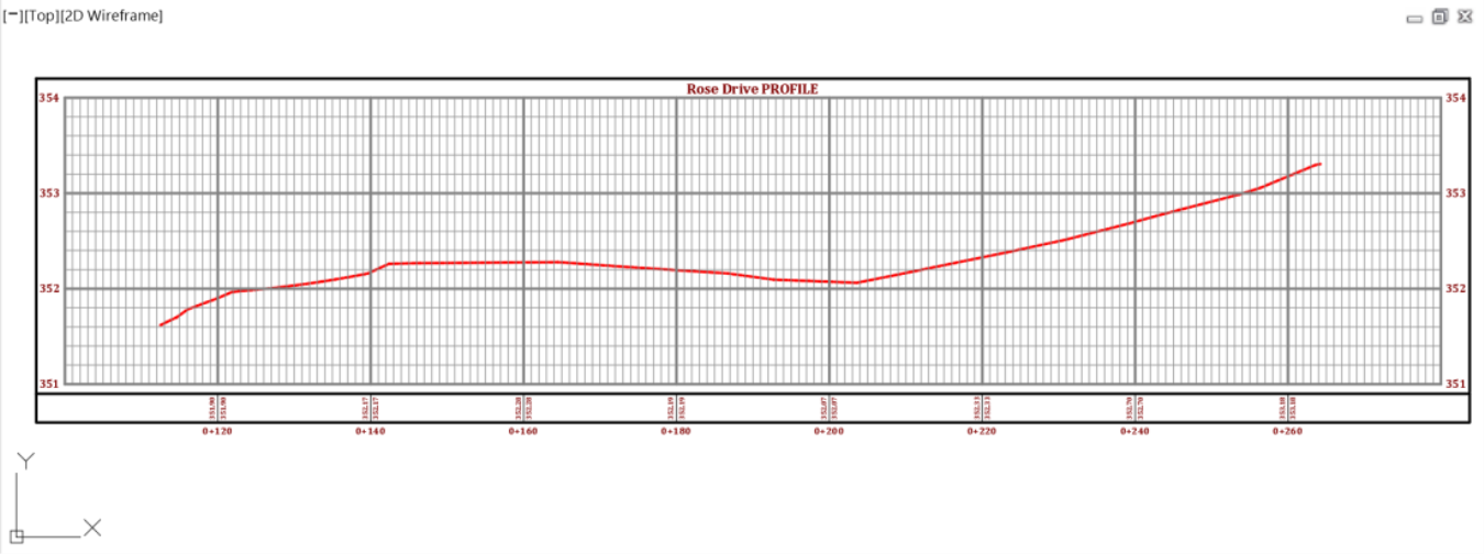
- From the ribbon, create a Surface Profile for the Existing Ground using the Rose Drive alignment.


- On the General page, you can specify basic information about the profile view. This includes the parent alignment, the profile view name, description, style, and layer. Click Next to accept. Later, you will be able to change any parameter you wish to adjust.

- On the Station Range page, you can specify the station range to which the profile view is drawn. The Automatic option specifies the full station range for the horizontal alignment. Whereas, User Specified Range limits the station range in the profile view to your specified values. Click Next to accept the current values. Later, you will be able to change any parameter you wish to adjust.

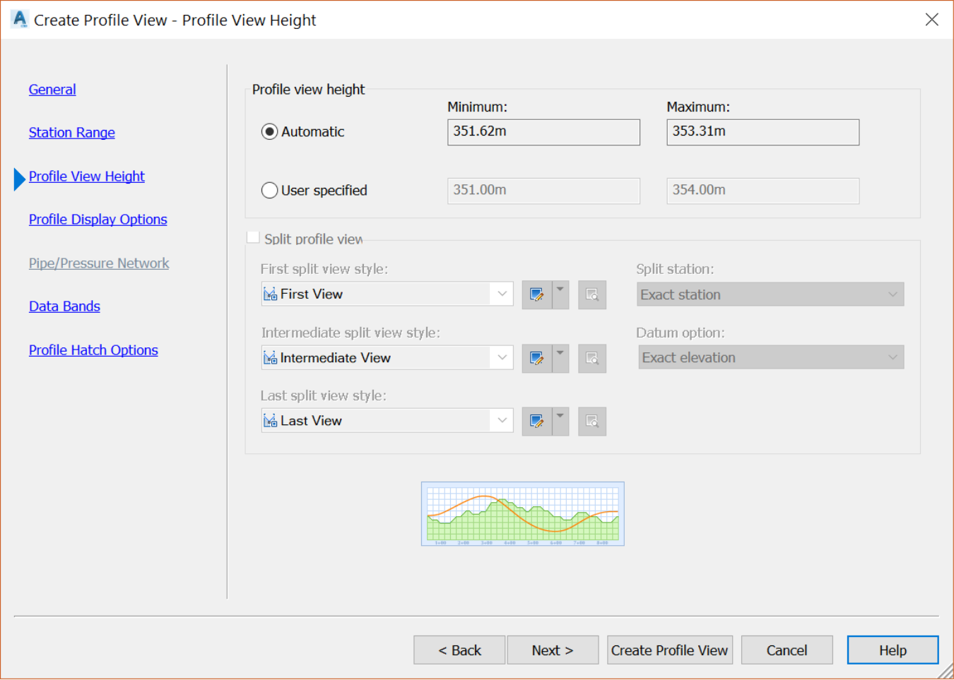
- Next is the Profile View Height page. It specifies the profile view height and any split profile view settings. The Automatic option means the full height of the highest surface profile. The profile view includes a buffer region above the maximum and below the minimum elevations. We will see how to set it in the profile styles. The User Specified option means you are specifying the height to which the profile view is drawn. If a surface profile extends beyond the user-specified value, it may be clipped. So, you need to have an idea of existing elevations before setting a User-Specified elevation. Click Next to accept current values. Once again, later, you will be able to change any parameter you wish to adjust.
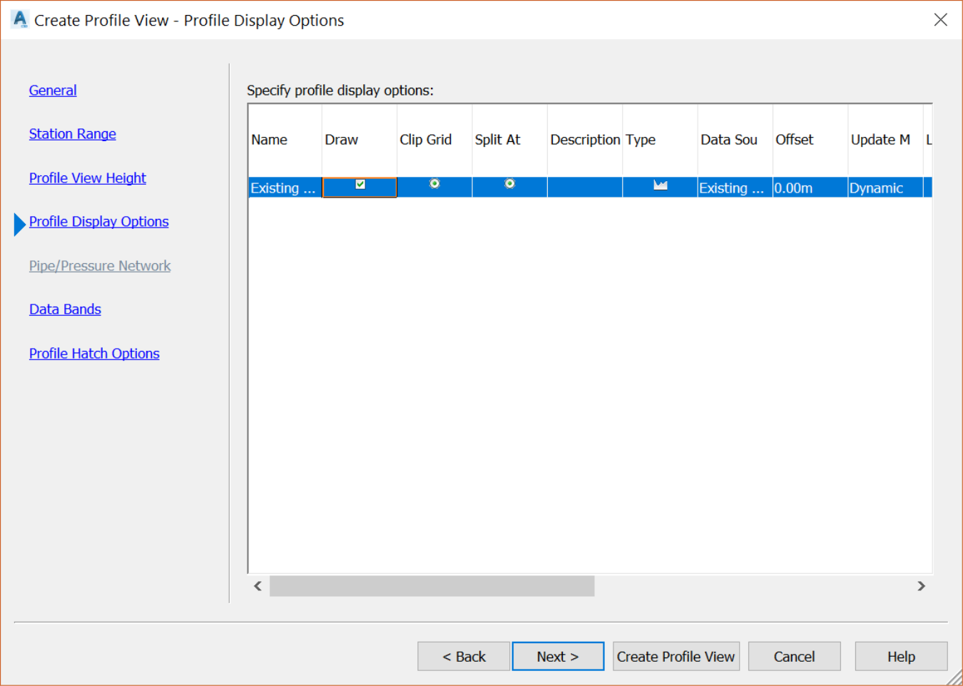
- Next, we have the Profile Display Options page. Here we can view and change the settings for all the profiles associated with the parent alignment of the profile view. Click Next to accept current values. As usual, later, you can make changes to any parameter if you wish to adjust.
- We currently don't have any Pipe Network in the drawing. So, the Pipe and Pressure Network page is grayed out and skipped.
- On the Data Bands page, we can specify the properties of the data bands associated with the profile view. For example, we have by default added a Profile Data BandType. It will display Profile1 and Profile2 elevations, at major profile stations. We can assign Profile1 to ExistingGround and Profile2 to Design Ground when we create the design grades later.

Finally, on the Profile Hatch Options page, we can add hatch areas to display cut and fill regions in a profile view.
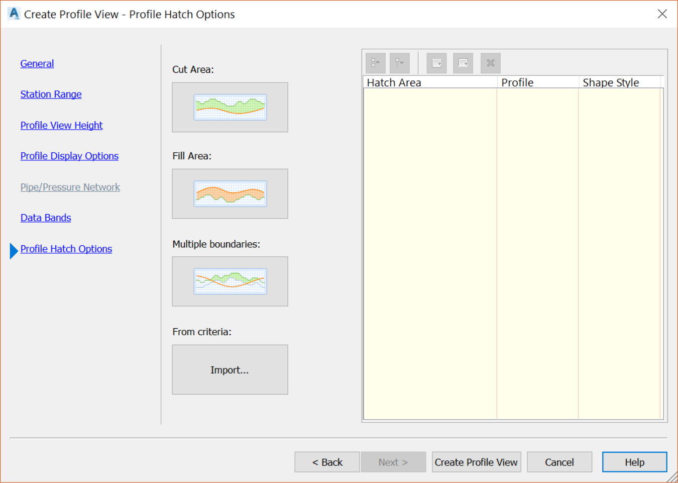
- Click Create Profile View to select a point in the drawing area where the lower-left corner of the profile view will be inserted.