-
Get It
$19.99
$19.99Civil 3D Essentials Book and Practice Files
Civil 3D Tutorial: Templates
Creating a Civil 3D template
Product: Autodesk Civil 3D | Subject: The ribbon Related: Civil 3D Essentials
In this exercise, we will use already existing civil 3d templates and styles, modify them, and create a file template for our future uses:
Open the 03.01-Styles-Templates dwg file in the Lesson 03 practice folder.

Let's start editing the file and establish some standards for object styles, units of measurement, labels, and the like. The creation and maintenance of template files is a never-ending process; It’s just a fact of life that we are always striving for a higher standard. Besides, projects and regulatory agency requirements are always evolving; our template needs to adapt accordingly.
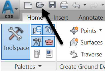
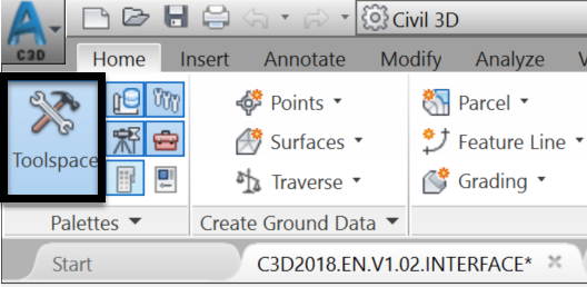
First, make sure the Toolspace is active and visible.
Civil 3D templates
Now, switch over to the drawing settings tab. Right-click on the file name, then Edit File Settings. Most standards (settings and styles) are created here. On this tab, we can create, copy, modify, or delete styles.


Under the Units and Zone tab, you can define parameters such as linear and angular units, annotation scale and the coordinate system.
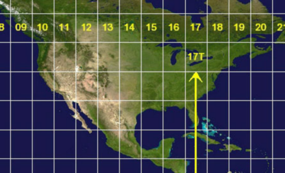
Let's set the coordinate system for this project. We will see why this may be helpful on the next tab. This site is in the Universal Transverse Mercator (UTM) projection system, Zone 10. Therefore, we chose the CSRS.UTM-10N system. We recommend that users consult their local Geographic Information System authority, for a recommended coordinate system for each project.
Next, we need to set-up the drawing to match the appropriate Units and zone.

The Transformation tab gives us an option to transform the coordinate system specified on the previous tab to a grid system. For example, if we have survey data that was collected using an arbitrary local system, we can transform that data into a known grid system. To do that, we must have at least two known reference points (for translation and rotation). Before any transformation, a coordinate system must also be set on the Units and Zone tab, which we already did by setting the projection to UTM North America Zone 10.
To make a coordinate transformation:
First, activate Apply the transform settings checkbox.
Then, pick a reference point in the drawing. Usually, this would be a point with known and georeferenced coordinates. In this case, our survey is already georeferenced. So, we are picking a random location, just to explain the process.
After that, type in the known coordinates of the point you selected, in the drawing in the previous step. This will complete the translation phase of the transformation.
Next, we need to perform the rotation phase. For that, activate the rotation option as shown on the Transformation tab.
Then, pick the second known point in the drawing. Again, click on a random point, to choose the second georeferenced point.
Finally, type in the known coordinates. Alternatively, you can use a rotation angle, if you know one.

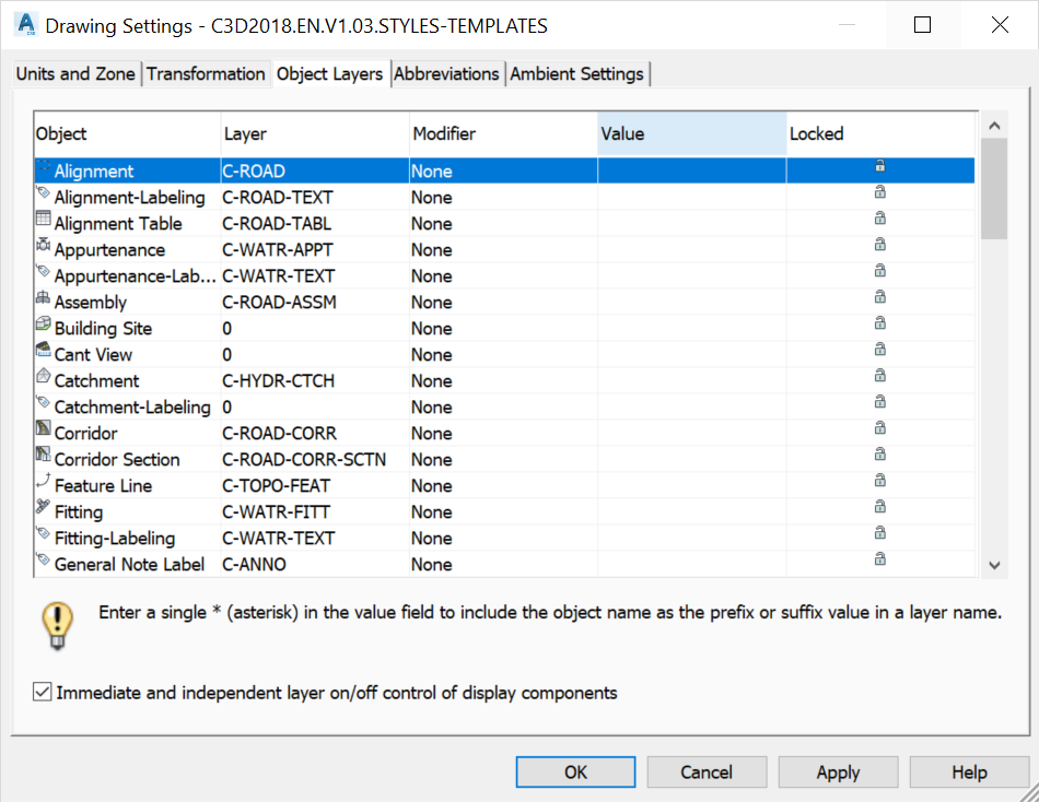
On the Object Layer tab, we can specify default layers for various objects; when we create an object, a Civil 3D point, for instance, it will automatically be placed on the layer specified here.
The Abbreviations tab allows you to manage different default abbreviations when creating labels and reports.

The Ambient Settings tab specifies the current file’s units and parameters.

You can change the units to meters or feet, square meters or square feet, cubic meters or cubic feet, and so on, by clicking on the “+” sign and opening the sections for Distances, Coordinates, Elevation, Area, Volume, and Station.
Saving Civil 3D templates
Now that some parameters have been created, save the file in a dwt format by proceeding as follows.

Choose the Lesson 3 working folder, that is the Templates tutorial folder.

Choose a DWT file format and click on Save.
Then, enter the description of the template. This part is optional, but as we will recommend throughout this course to always try to provide self-explanatory descriptions.

Click on OK to create the template. Now, every time that we are starting a project, we can open this template file and rename it.
Defining Civil 3D Default templates
As an option, we can also define this file as a template. It would be loaded whenever we create a new drawing (using the QNEW command). To set the default template, use the following steps:
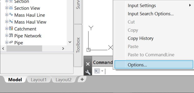
Type Options at the command line or right-click in an empty space of the drawing area and choose Options.
Browse to choose a default template file:

Then, find and select the template file you would like to use as default and click on Open.

We have, at this point, defined the default template file to use each time we create a new drawing. For now, click on Cancel as we are just practicing and do not wish to change any setting that will affect your production.

Now, we know how to create a template file and how to set it as the default for creating new projects.
The next step is to maintain and improve the template with new styles, as we are creating them.
Full Course and Free Book


Customer Reviews
Great course
Patrick Butler
Very interesting and easy to understand. Since I already have some experience, was good to see how to design using different methods. Definitely further my knowledge even more. Can't wait to take more advanced courses. Thank you!
Very interesting and easy to understand. Since I already have some experience, was good to see how to design using different methods. Definitely further my knowledge even more. Can't wait to take more advanced courses. Thank you!
Read LessTutorial: Civil 3D
Introduction to Civil 3D
What is the Civil 3D? Let's find out in this online training course and tutorial, a part of the Civil 3D essentials book and how-to manuals.
Topic: Civil 3D | Training: Civil 3D Essentials | Software: AutoDesk Civil 3D
Civil 3D course OFFER
Refer a friend and both of you get access to our Civil 3D Courses at a discounted price.
Related Civil 3D Course and Books