• $19.99

    $19.99Civil 3D Essentials Book and Practice Files

    Get It

Let's learn about Civil 3D Description Keys in this online tutorial, a part of the full Civil 3D essentials online training course. 

Description Keys

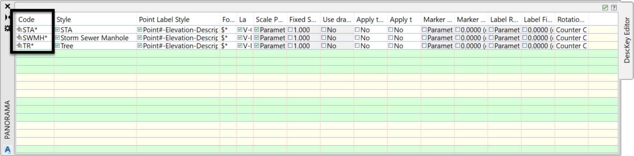
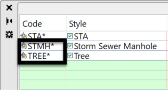
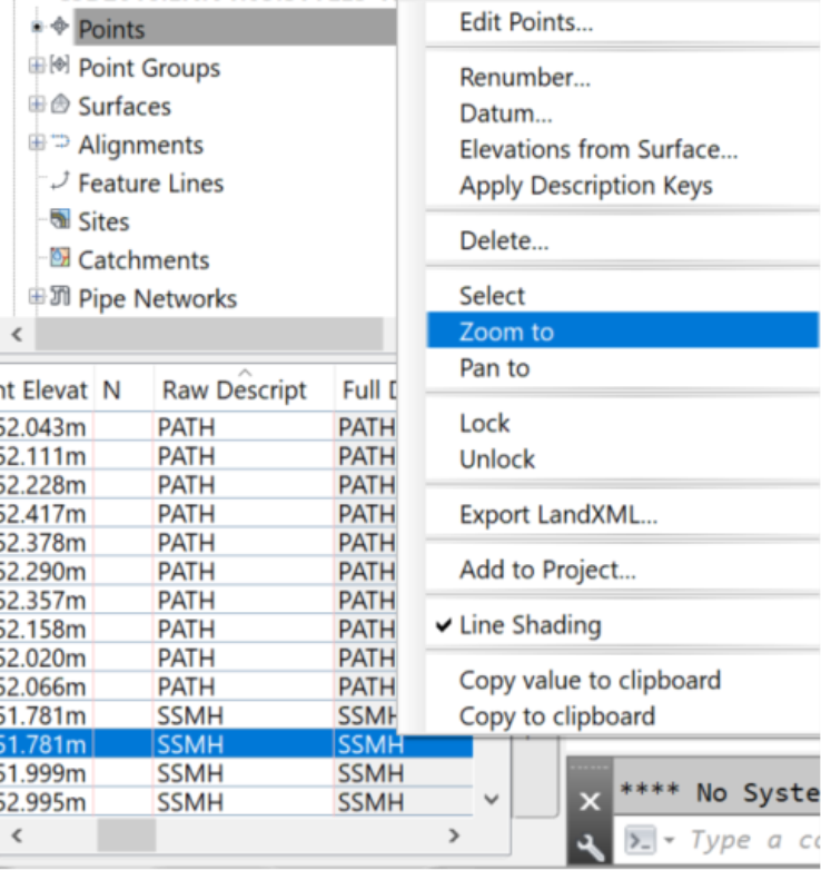
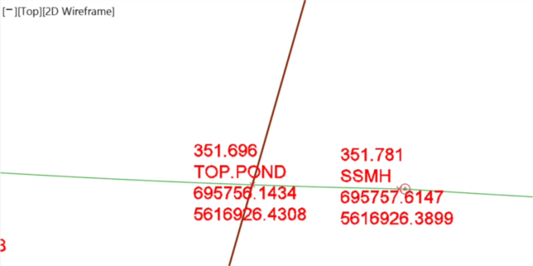
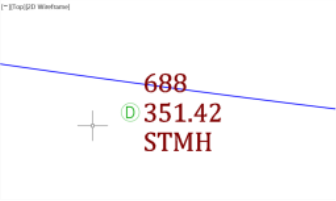
One of the most common land surveying post-processing operations is to assign symbols to survey points to give them a distinctive and self-explanatory appearance. For example, we would like to show specific symbols for trees, fire hydrants, manholes, andthe like. Traditionally, this is done in AutoCAD by using a library of blocks. Now, this process can be automated in Civil 3D by using description keys. Description keys can be applied during or after the import process. They just need to be created and defined before the points. If not, an update must be made to the point group to apply the description keys.  

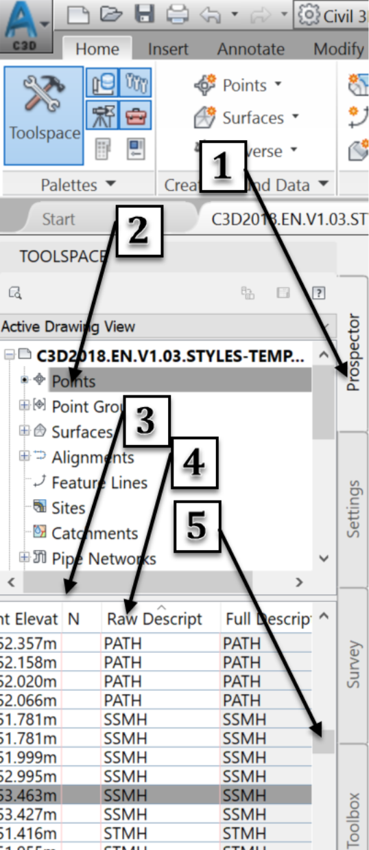
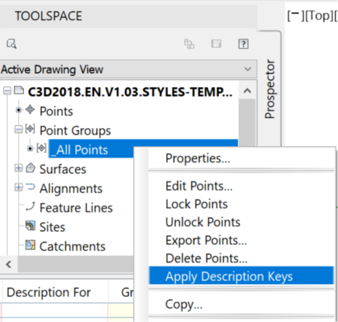
Let's see how to apply styles and labels to survey points, using a Description Key Set.

  1. First, we need to define the Description Key Set.  To do so, you can edit the existing description key set (IC.Desc.Key). You can also start with the out-of-the boxCivil 3D key set, if working from the default template file.
  1. Another option is to simply create a new set by right-clicking on Description Key Sets on the Settings tab, in the Toolspace. You can choose either option for this exercise.  But, just to be consistent with the steps in this training, let's pick the option to edit the existing Description Key Set


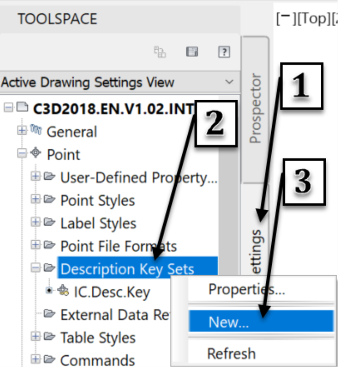
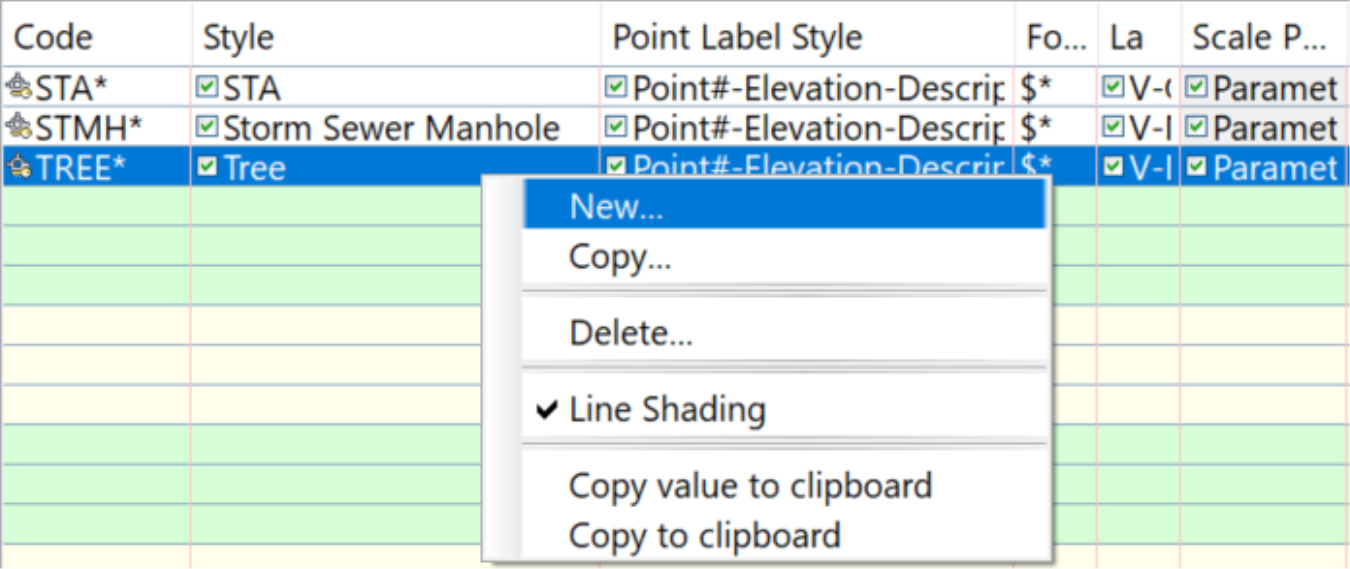
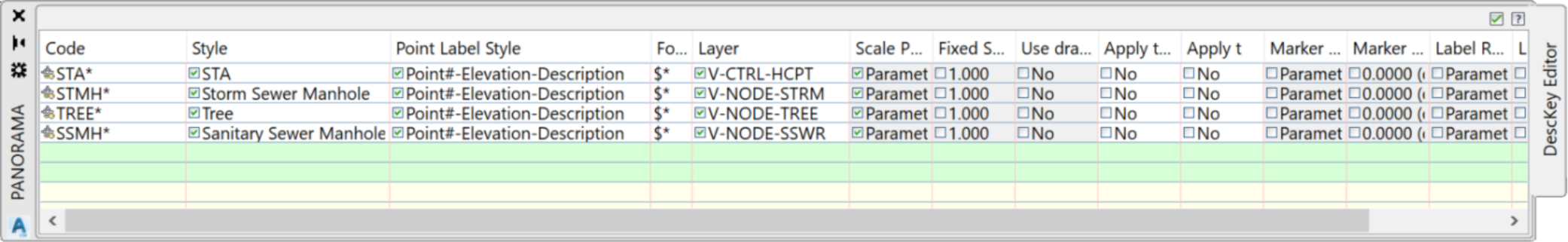
To Create a New 

Description Key Set

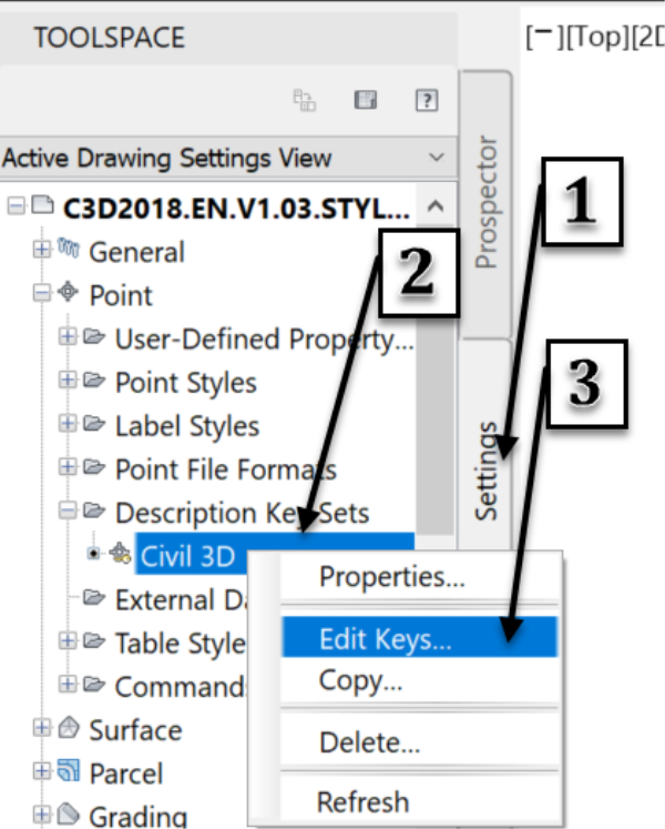
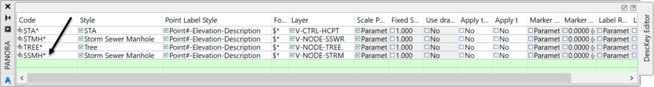
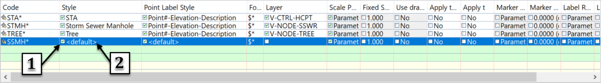
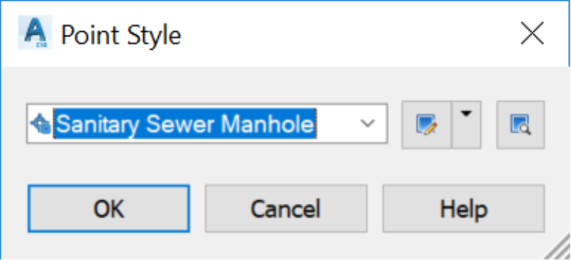
To Edit an existing 

Description Key Set


  1. In the Panorama Window, that we will encounter in Civil 3D whenever we need to edit an object in a tabular view, we have a few pre-defined codes (STA* for Station, SWMH* for Stormwater Manholes, TR* for Trees). C:\Users\INFRAT~1.CIV\AppData\Local\Temp\SNAGHTML2b5f0be.PNG
  1. Now, we need to modify a couple of the pre-defined codes to match our requirements. In our survey file, Storm Manholes are described with the code STMH instead of the code SWMH used in the description key set. Also, our surveyor used the code TR for the trees and not TREE, as described in the key set. So, we need to make a change to the code, to match the description used in our survey file. Click on the two codes to rename them to STMH and TR respectively. C:\Users\INFRAT~1.CIV\AppData\Local\Temp\SNAGHTML2bde4e0.PNG
  1. Next, we want to create a code for the following items: Sanitary Sewer Manhole (SSMH), Fire Hydrants (FH), Water Valves (WV), Existing Ground (EG), and Light Poles (LP). Let's start with the SSMH. To create a description key, in the editor vista (Panorama window), right-click on any line and click New.


  1. A line is added to the Description Key Set.

     
  1. Now, edit the new Description Key to match the codes in our current and future survey files: rename the new Key to SSMH*. We should mention that contrary to point groups, and other definitions in Civil 3D, all entries in the Code column of the Description Key Editor are case sensitive. Therefore, we should be mindful of that.
     

C:\Users\INFRAT~1.CIV\AppData\Local\Temp\SNAGHTML2e5049f.PNG
 

  1. Next, apply the style for SSMH to determine the appearance of the points. For all SSMH points, select the Sanitary Sewer Manhole style.
     

  1. Repeat the previous two steps to change the Points Label Style to Point Number-Elevation-Description. Then, assign the layer to V-NODE-SSWR.


  1. The new Description Key windows should be all set now and ready to be utilized.
     

C:\Users\INFRAT~1.CIV\AppData\Local\Temp\SNAGHTML2e97d27.PNG

  1. However, before going further, we should make a couple of observations:
  1. The asterisk is a wild-card character that allows us to apply a catch-all definition to a code, followed by any other character. For example, STMH* will include STMH1, STMH-2, STMH-Ex, and so on. We must also note that, when a Point or Label style is not applied from the Description Key Set, the Point Group properties will take precedence and control the style and label style.
  2. Finally, the $* sign in the format column specifies that a point’s raw description will be used as full description in the point label.  If we want a different value for raw and full description, this is the place to specify that.
  1. Now we know how to create Description Keys. We can use these steps to create a full Description Key Set for our company. A sample more advanced description key set will be provided for your use, in the Infratech Template file included in the resources provided, as part of this training.
  1. We can now close the Panorama windows by clicking on the green checkmark at the top right to close the Description Keys Editor.
  1. Let's check what happens to the points for which a description key has been created.
  • Activate the prospector tab in the Toolspace. 
  • Click on Points
  • Re-arrange the Panorama (table at the bottom) to display the Raw Description column, 
  • Sort the points by Raw Description
  • Scroll down or up to display the point description SSMH.
     

  • In the table, select one of the points with SSMH as raw description, right-click and Zoom to.
     

  • The point is displayed in the center of the screen. We need to zoom closer.
     

  • We can see that the point is shown just like any of the other points. The reason for this is that we have created the Description Keys after the points have already been created or imported. Therefore, we need to apply the Description Key set to points that have already been created, before the key set.  
  • To apply the keyset, go to the point group, in this case, the _all points, select it, right-click and click Apply Description Keys.
     

  • Now, notice how the Points style and Label style have been changed to the specifications in the KeySet table?


Training:  Civil 3D Essentials    |  Topic:  Civil 3D Description keys    |    Software:  AutoDesk Civil 3D