-
Get It
$19.99
$19.99Civil 3D Essentials Book and Practice Files
Civil 3D Pipe network by objects: A step by step tutorial guide
Introduction to Civil 3D Pipe network by objects
Firstly, what is a Civil 3D Pipe network by objects? Well, let's find out in this online training course. Certainly, this step by step tutorial is a part of the Civil 3D essentials book and how-to manuals.
Working with Civil 3D Pipe network by objects
Now is a good time to refresh ourselves with the requirements from the municipal code regarding utility layout.  Looking at the typical section, storm sewer pipes need to be at a 1m or 3ft depth offset from the centerline, with a minimum of 1m or 3ft cover.
Pipe networks can be created From Object or by using the Pipe Network Creation Tools.
Let’s create the network using the object-based method first. To do that,
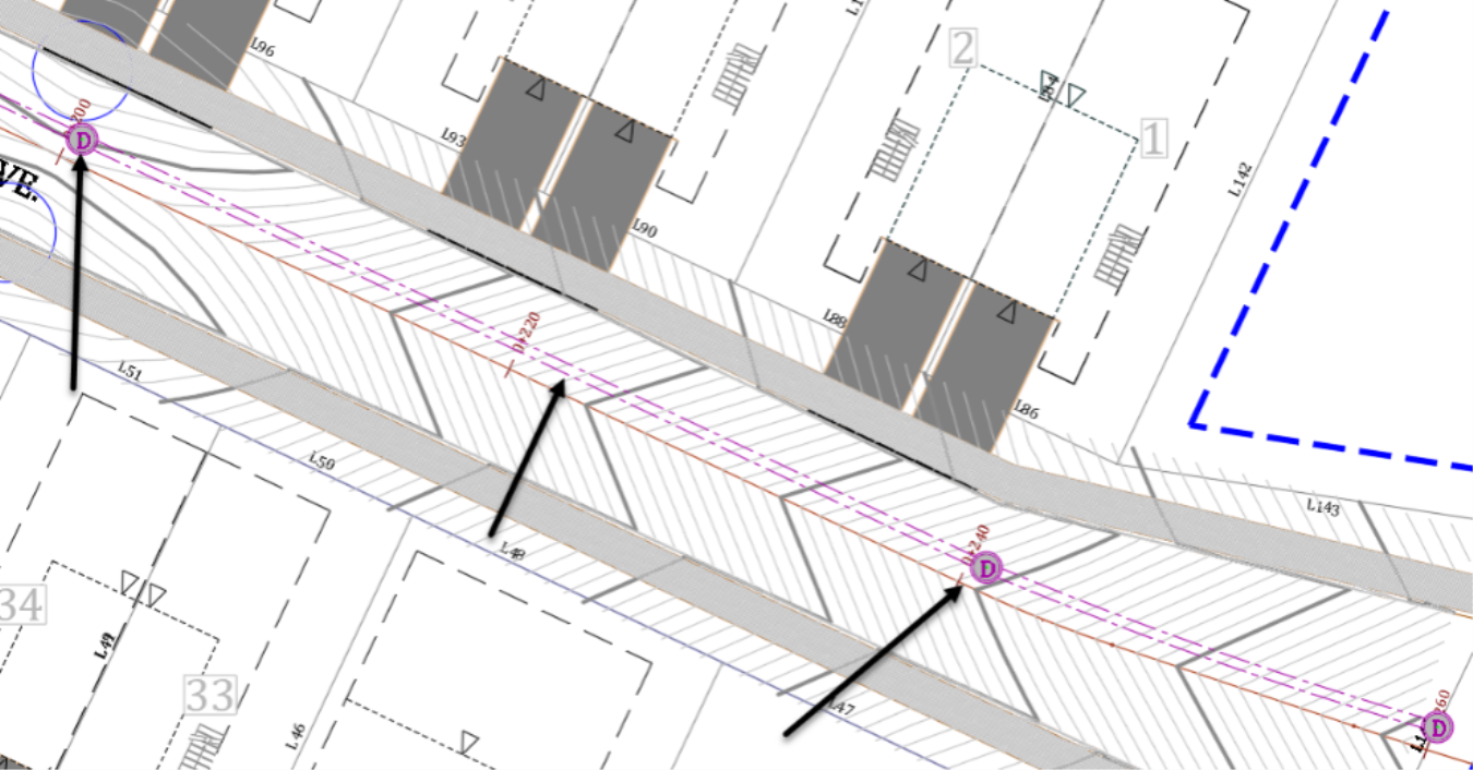
- Select the centerline of the Rose Drive alignment.

- Offset it 1m or 3ft to the north by using the AutoCAD offset command or typing the alias O at the command line.
- When prompted to Specify Offset distance at the command line, enter 1m or 3ft and press Enter.
![]()
- When prompted to specify a side, click north of Rose Drive Alignment.
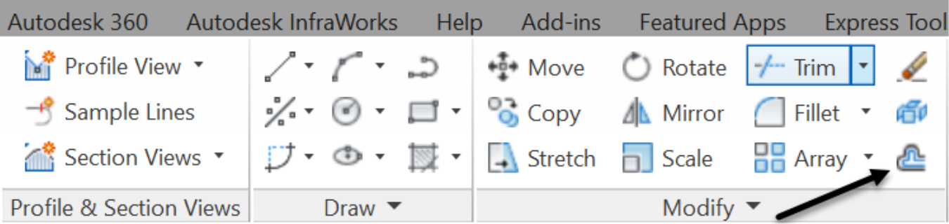
- The new line object will represent the centerline of the stormwater pipe network. Therefore, we need to assign elevations to the line, so that we can set the pipe invert elevations. For that, we need to convert the polyline to a more powerful type of object: Feature lines. They are predominantly grading entities that can interact with other objects. In this case, we use them due to the ease of use presented by their visual editor and geometry editing tools. To create a Feature line object from the offset centerline, run the Create Feature Lines from Objects command from the ribbon.

- Select the polyline object created by offset and press Enter at the command line.
-
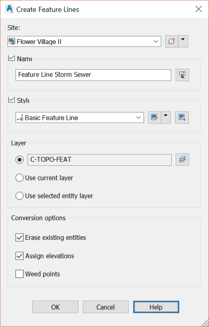
In the Create Feature Lines window,
- First, we need to assign a Site. We talked about sites before, they are topological containers where we can put entities that can have an interactive relationship. In this project, we only have one site, so our feature line object will reside in the Flower Village II site.
- Next, name the feature line object and select a style, say Basic Feature Line object style.
- We will leave the layer to the default one.
- Last for the Conversion Options; we will erase existing entities and assign elevation. However, there is no need to weed points on the polyline object. The polyline has a fairly reasonable number of points and is on an almost straight path.
-
Click OK.
-
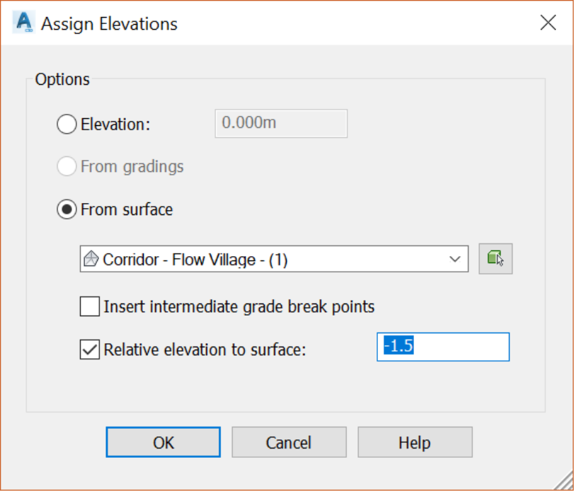
In the Assign Elevations window,
- Assign elevation from the corridor surface,
- Set a relative elevation of -1.5m or -5ft for the pipe invert. We are required to have a minimum cover of 1m or 3ft, but we still need to account for the pipe diameter. So, we are adding an additional 0.5m or 2ft. If we need to add or reduce the pipe cover, we can always raise or lower the feature line object by selecting it and using the raise/lower command. At this stage, we still don’t know the final sizes of the pipes. This will be established in the stormwater modeling phase of the design. Please refer to the Advanced Civil 3D – Stormwater design module of our courses.
- Now, click on OK.
- The polyline is now converted to a Feature Line object. Once it is selected, the contextual ribbon displays all feature lines object-related commands.
- Let’s use a few of the Feature Line object editing tools.
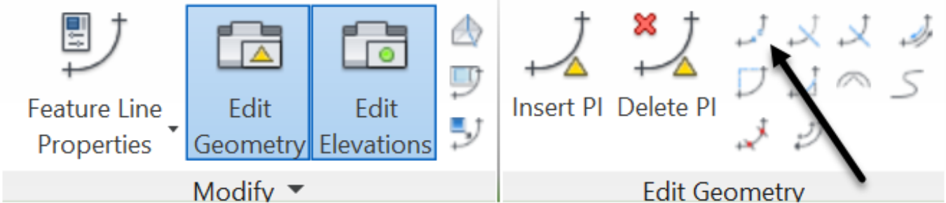
First, Break the feature line object to contain it inside the project. It’s worth mentioning that regular AutoCAD commands such as break and trim will not work on feature lines. They have their own set of commands. We can run them from the Edit Geometry or Edit Elevations panels of the contextual feature line ribbon. So, while you have the feature line selected, click on the Break command in the Edit Geometry panel.
When prompted to select an object to break at the command line, click on the Feature Line, at the eastern or western end of the site boundary.
When prompted to specify the second breakpoint, click outside the site area on the feature line.
The feature line object is now broken in two. We can simply delete the part that falls outside of the site.
Now repeat the same operations, break and delete, on the other side of the project.
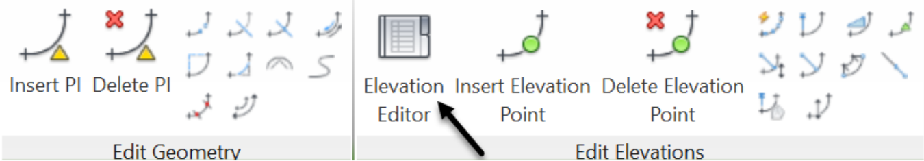
- Because we are never too sure, let’s check the elevations of the Feature Line before using it to create a pipe network by objects. Select the feature line and in the Edit Elevations panel, display the Elevation Editor. You can also display it by selecting the feature line, right-clicking, and choosing Elevation Editor.
- Once the Elevation Editor is displayed, in the panorama window, you have all the vertices of the feature line in a tabular view. You can also see their associated stations, elevations, distances and grades between points. All data in this window, except the lengths, can be manually adjusted. Depending on where you broke the feature line you may need to adjust the elevation of the points at the extremities. If the surface falls out of the Corridor Surface we assigned our elevations from; their elevations are not going to be correct.
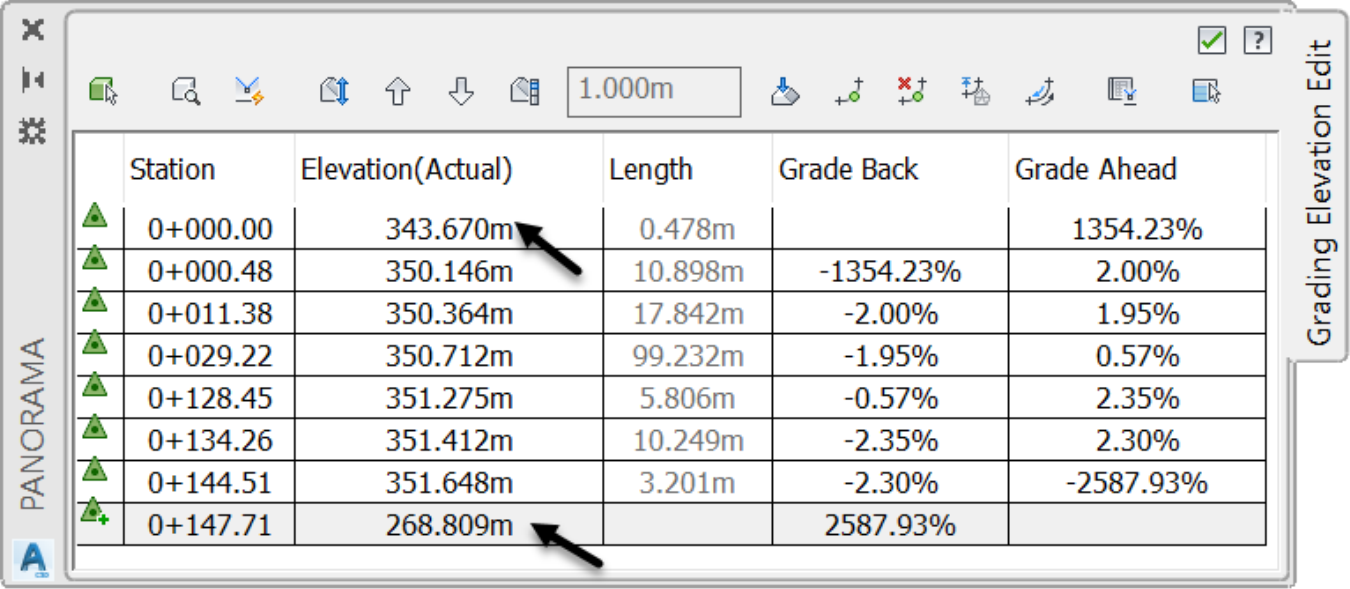
- In this case, to fix the elevations at the two extremities of the feature line, we will simply assign a 2%Grade Ahead and -2%Grade back. This allows us to change the elevations only at the extremities.
- Click on the green checkmark to dismiss the Panorama vista. Your changes will apply to the feature line.
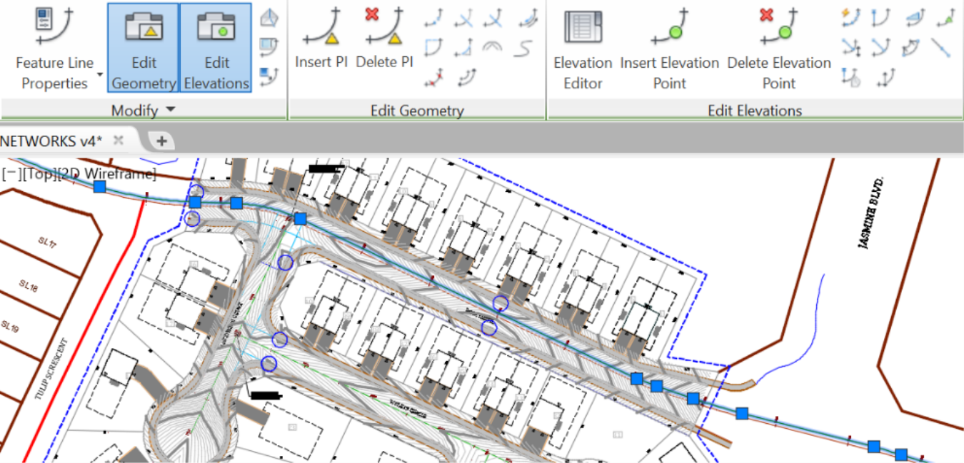
- Next, we need to delete the unnecessary vertices, because stormwater structures are going to be created at all vertices. Note that we can go ahead and create the network and adjust it later to remove the extra parts. But we have an opportunity here to learn more about the feature line editing tools, and we don’t want to miss it. So, select the feature line and zoom to the east end of the site, just before the roundabout.
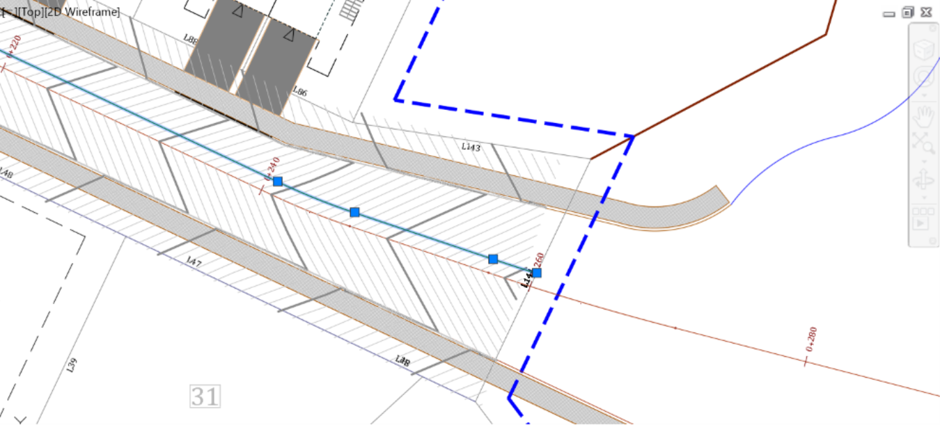
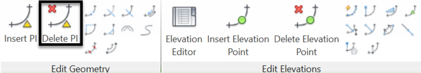
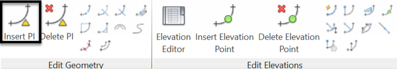
- We obviously don’t need manholes at all the shown vertices. So, delete the two middle vertices. We need to keep the westernmost one to meet the maximum pipe length of 120m or 400ft. We also need the easternmost one to allow future connections to our project by others. To delete feature line vertices, first, run the Delete PI command on the ribbon.
- When prompted to specify the point to delete, click on the two middle points.
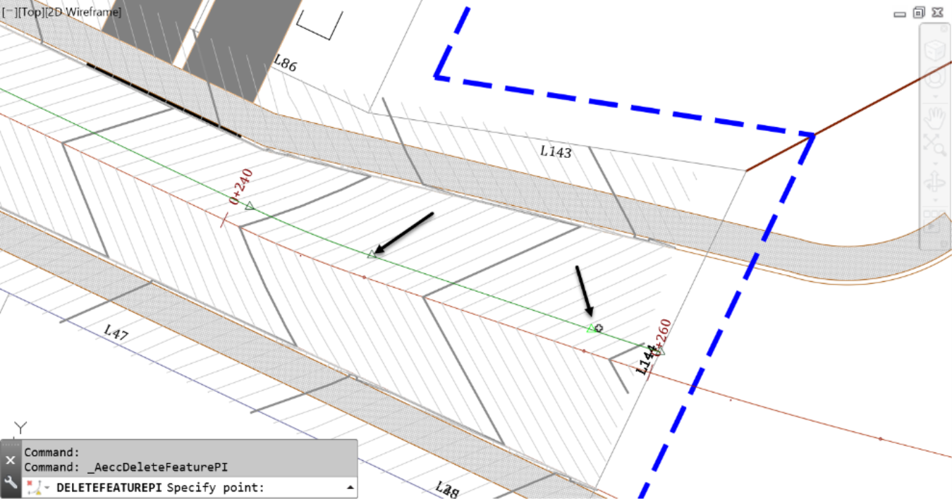
- We now have two locations for future manholes.
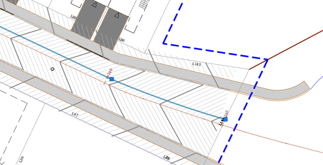
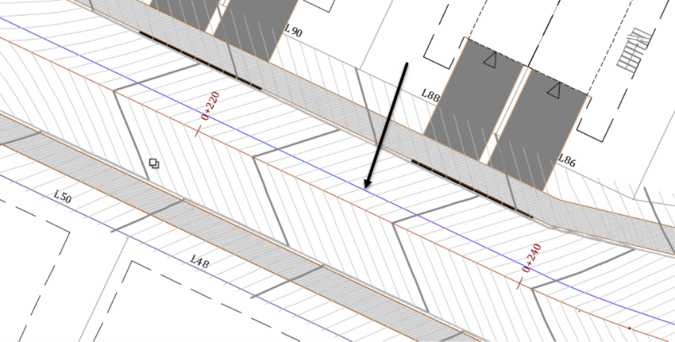
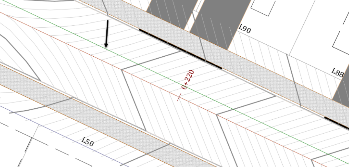
- Moving westward, we see the two spots we reserved for catchbasins. That means we need a manhole in the vicinity to tie the catchbasins to. So, this time instead of deleting, we need to insert a vertex.
- Run the Insert PI command.
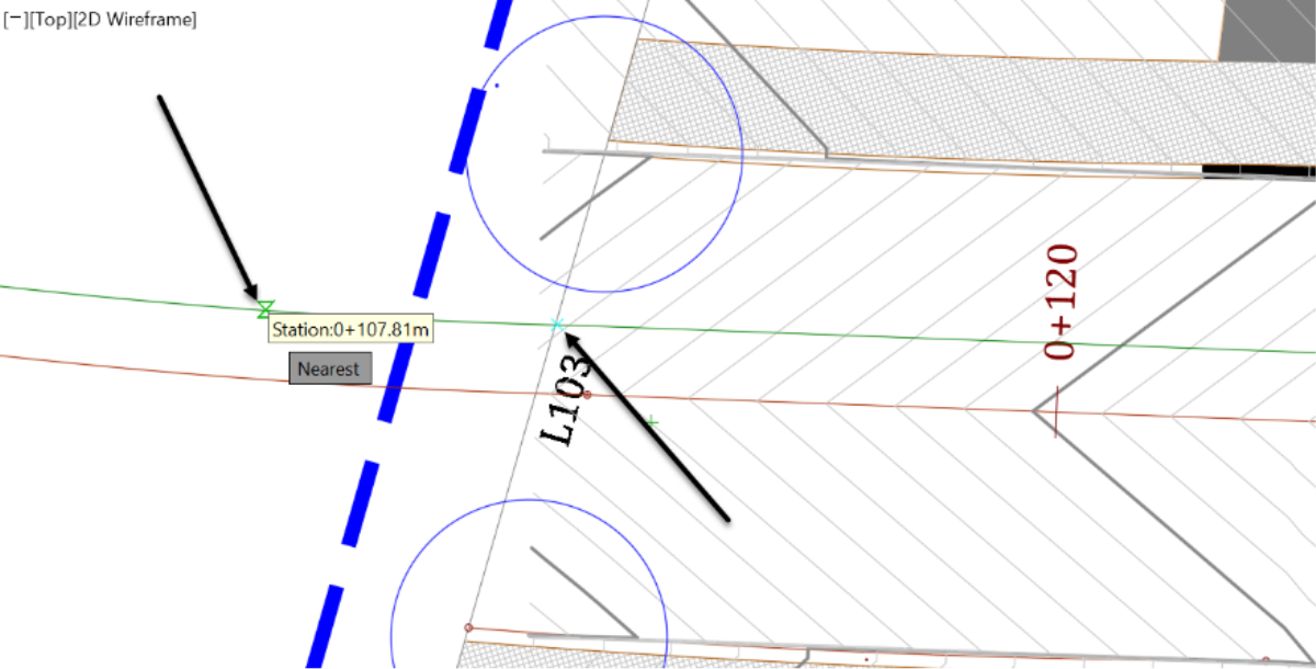
- Then, click approximately between the two future catchbasins, on the feature line.
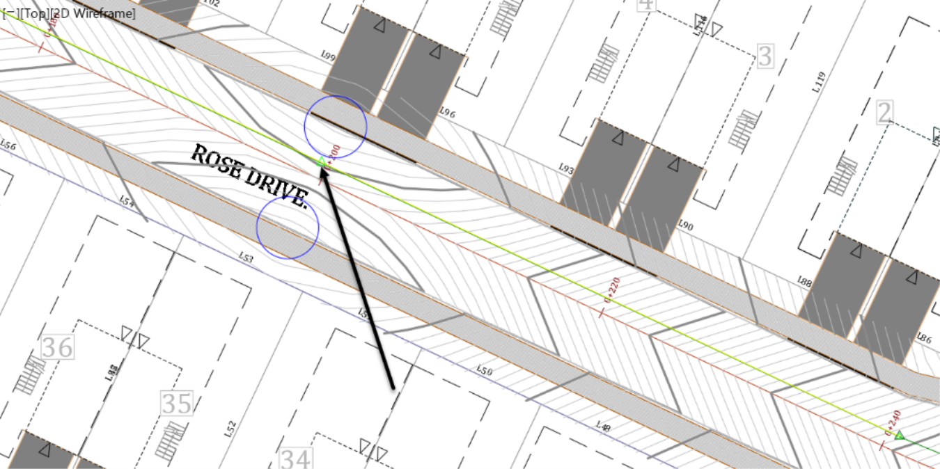
- The elevation is automatically calculated using the feature line slopes. Press Enter to accept it. You can change it if needed, but there is no point in this case since these are just temporary elevations. We just need something reasonable to lay out the pipe network.
![]()
- Next, press Escape to exit the PI creation command and move down the road to the intersection area. Here, we need to get rid of two more vertices. However, we need the structure at the end of the curve to keep the nice smooth curve. We can have a curved pipe if we are using a flexible pipe that can be bent. If not, we then need to convert that segment of the feature line to a straight line, using the EditCurve
 command. So, let’s only remove the second to last vertex towards the end. This way, we can tie the end catchbasins to the last vertex and the intersection's catchbasin to the first vertex. The remaining vertex can also be a catchbasin or a null structure. If a catchbasin is not needed there, when we make our final decision, we can remove it, using the Delete PI.
- For now, our feature line is set up, and we can create the pipe network from objects.
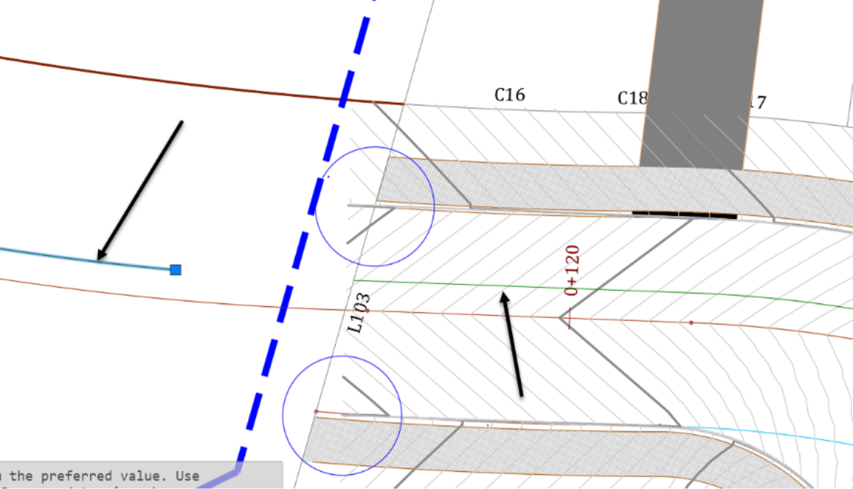
- From the Home tab of the ribbon, run the Create Pipe Network from Object command.

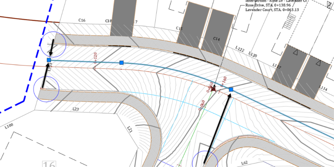
- When prompted to select an object, click on the feature line towards its eastern end.
![]()
- This will show the flow direction from east to west as we needed. If you have the flow in the opposite direction, you can always type R at the command line to Reverse it.
- Press Enter to accept the flow direction.
-
Now, we need to enter the network details in the Create Pipe Network from Object window.
- For the name, we will go with Storm Sewer.
- Use a description of your choice, like Phase 2 Storm Sewer network.
- Then, assign the Network parts list to use to Storm Sewer.
- For Pipe to create, choose a 450mm or 18in size pipe. This should be good size pipes, due to the high slopes we have. As mentioned before, the final sizing will be done in Storm and Sanitary Analyses, or SSA for short. It is the pipe modeling software that comes embedded in Civil 3D.
- For Structure to create, select a 1,200mm or 48in diameter, cylindrical Structure.
- Leave the layers to default.
- For surface, select the road corridor surface. This is the reference surface from which pipe rules will be applied.
- For Alignment name, choose Rose Drive. This will be the alignment from which structure stations and offset will be referenced.
- We will not Erase the existing entity, just in case we need it later.
- Check the box to Use the vertex elevations. After all, this is the whole point of the lengthy process of creating feature lines and assigning elevations to them.
-
Finally, check the Outside Top to use as feature line elevations. This will be the point where the cover is estimated from the final ground. Remember, we added an extra cushion of 0.5m or 1.5ft when we were creating the feature line. The reason was to account for the pipe diameter. That will not be needed if we are going to use the Outside Top. Nonetheless, let's accept the extra cushion. If in the end, we have enough room, we can raise the whole network to bring it to within the required 1.5m or 5ft cover.

- Now, click on OK.
- The pipe network, created from objects, appears in the drawing area, and also in the prospector. Next, we will see how to create and modify pipes using the Pipe Creation Tools.