-
Get It
$19.99
$19.99SSA Stormwater Book and Practice Files
Storm and Sanitary Design Tutorial: Nodes
Stormwater Nodes in SSA
Product: Autodesk SSA | Subject: Storm and Sanitary Analysis
In this exercise, we will learn about stormwater SSA nodes.
4.5.1 Nodes
4.5.1.1 Junctions
In the Nodes category, we have already set the Junctions (manholes) during the Part Migration process in Civil 3D. So, we don’t have much work to do here. But, just to make sure nothing got lost in the process:
- Keep working with the same file if you are following along. If not, open the file 04.04-SEWERS-Hydraulics-Nodes.spf
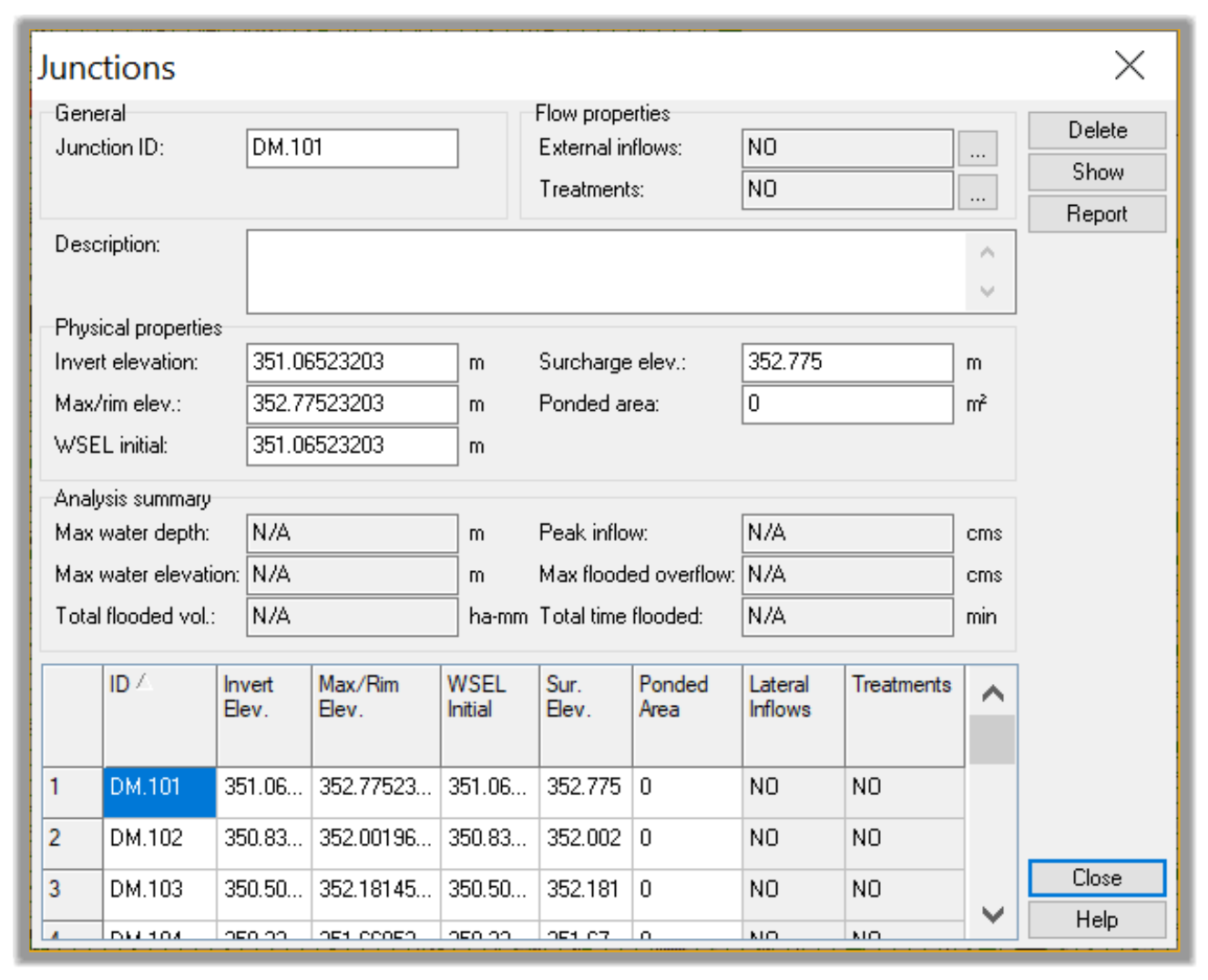
- Let’s double-click on the Junctions line.

- We can make sure all our manholes from Civil 3D are present and have the exact values for the rims, sumps, and the likes.
4.5.1.2 Storage Nodes (Ponds)
Next, we can move to the next item in the hydraulics section, which is the Storage nodes. Storages are used for ponds. Even though we will perform the final design of the pond in the detention section of the course, let’s import the data as laid out in Civil 3D.
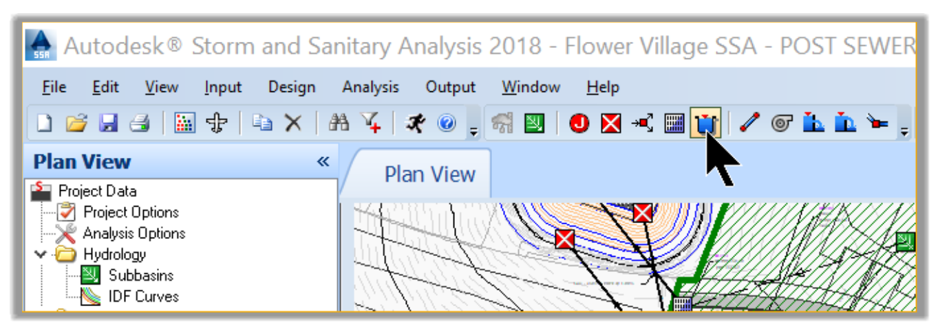
- Now, let’s see how to use the item creation tools on the toolbar. We have not used them so far, but they are straightforward. The standard ones are used for Standard operations such as saving, opening, printing, and others. The Map commands are for selecting, measuring, and similar operations. The Elements commands allow us to create elements and the Outputs commands are for exporting or analyzing the network.
Standard ![]()
Map ![]()
Elements ![]()
Output ![]()
- To create an element, click the symbol and drop the elements on the map at the desired location. Let’s see this in practice by creating a pond. Click on the storage element.
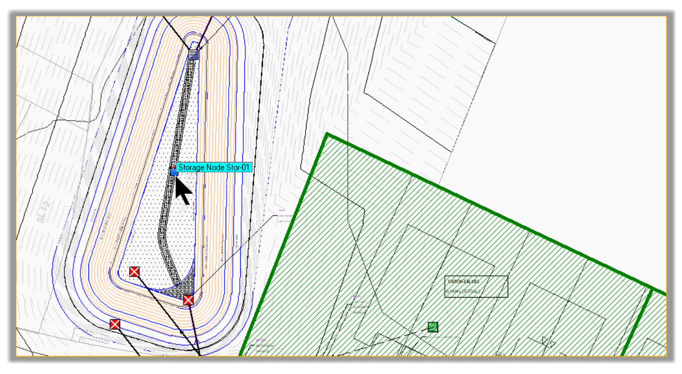
- Then, drop it in the middle of our pond.
- Next, we need to design the pond. In stormwater pond design, one of the basic inputs required is the pond Stage Storage information. This will be the information needed by the routing model to determine elevation reached in the pond, using the difference between inflow and outflow volumes.
- First, let’s enter the pond data. Double-click on the pond, in the plan view.
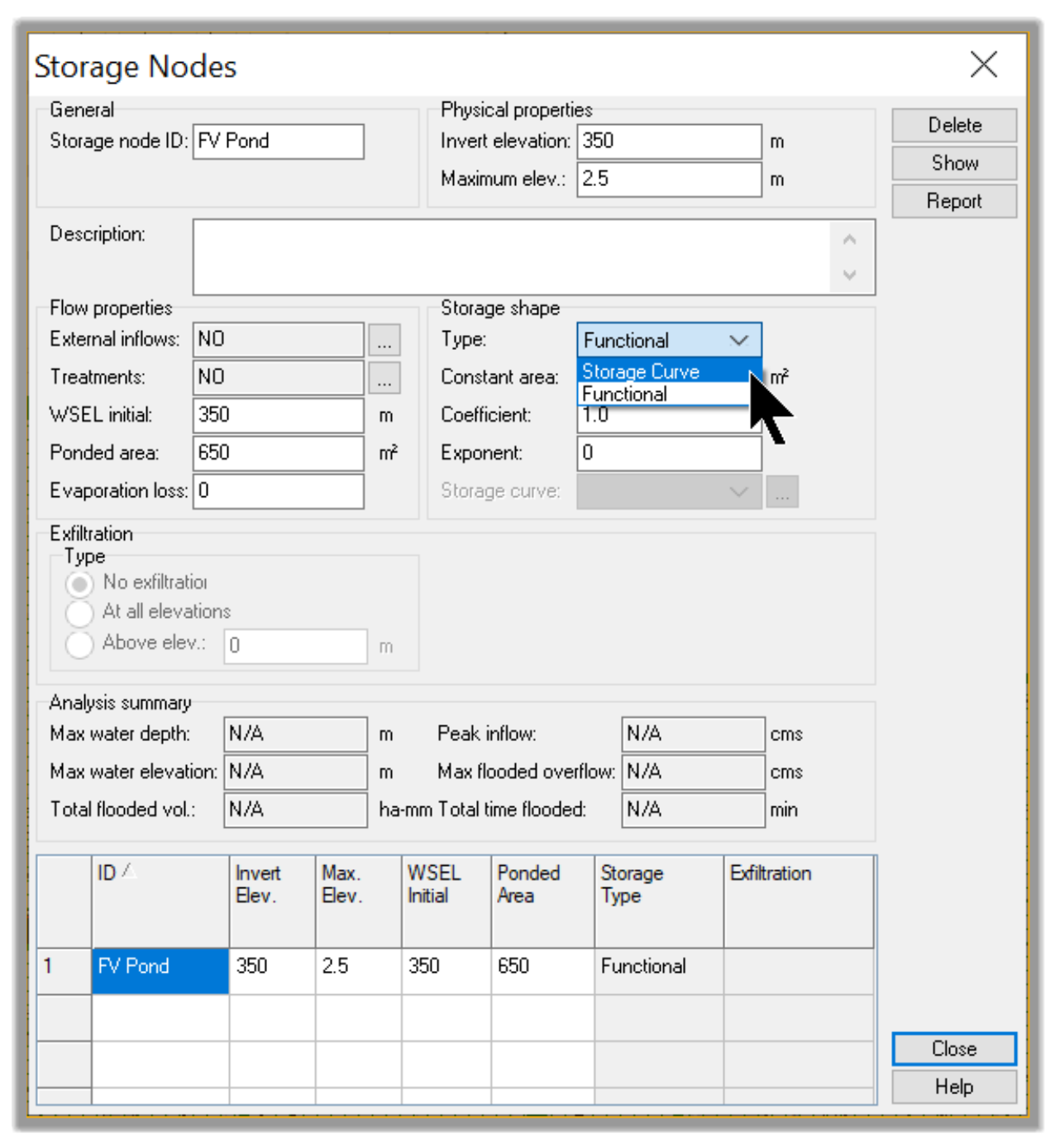
- The Storage Nodeswindow opens. In the new window, let’s set the following information.
- FV Pond for Storage ID
- 350m or 1,150ft for the invert elevation. This information is obtained from the pond in Civil 3D
- 352.5m – 1,156.50ft for the Maximum elev, including the freeboard
- 350.60m – 1,150ft for the WSEL Initial (that’s the Initial Water Surface Elevation). We are setting the initial water elevation 0.6m (2ft) higher than the invert because we are required to have a 0.60m permanent pool for the water quality.
- 650m2 or 2130 ft2 for the ponded area.
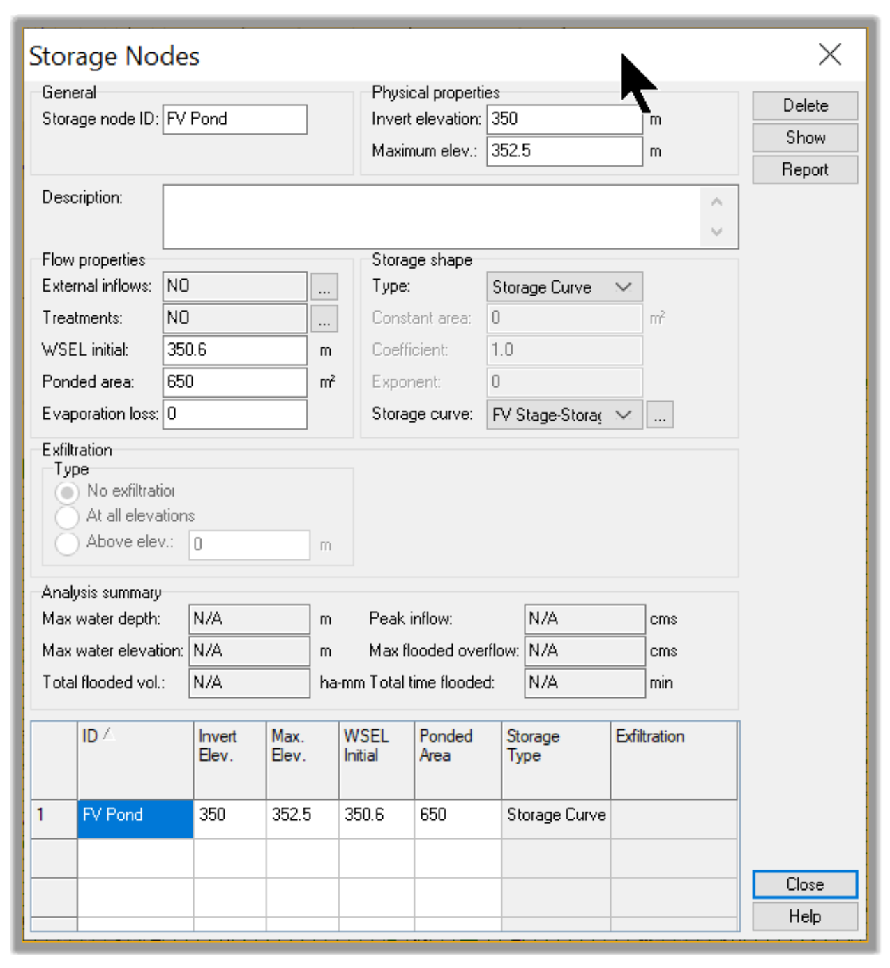
- Now, we need to define the Storage Shape, and there are two options to do that. We can use a functional type to specify a constant surface area, coefficient, and exponent that will describe a functional relationship between the depth and the surface area. It’s basically a stage-area expressed by a formula. This method is suitable for standard shapes such as storage tanks. However, most of the time a Storage Curve is more practical. So, let’s choose the Storage Curve option.
- Next, click on the ellipsis
 to enter the Storage Curve information
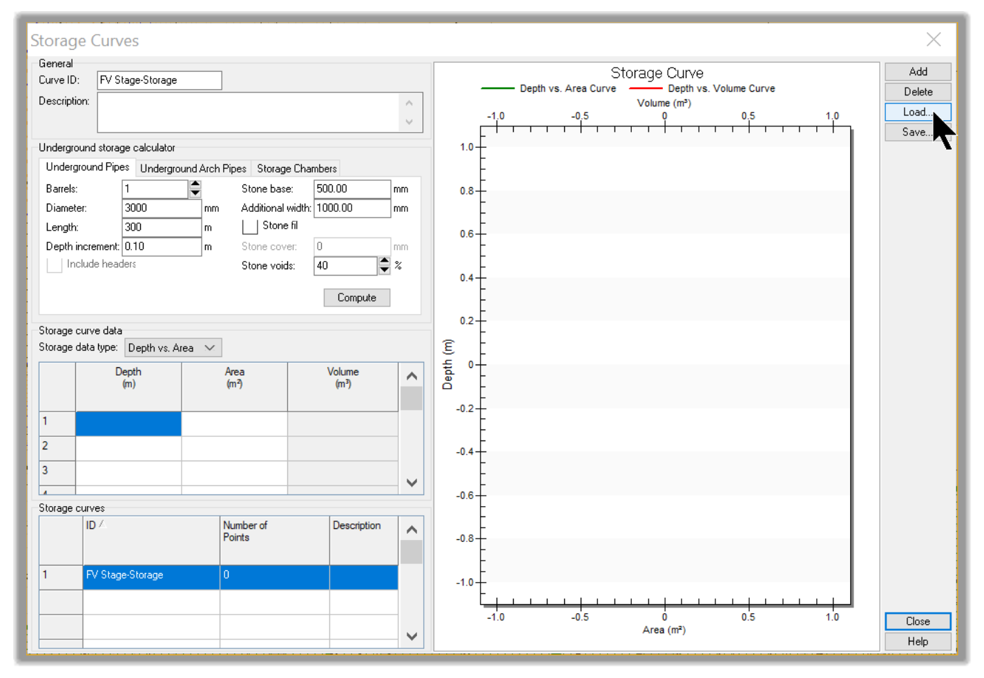
 - In the Storage Curves window, click on

- Change the Curve ID to FV Stage Storage. In the Stage Storage Curve data area, we have two options: Depth vs. Area or Depth vs. Volume. Activate Depth vs. Area.
- Next, we can type or paste the Depth and Area information if we have it available, say in a spreadsheet. However, since we have already exported it from Civil 3D, we can load it. Click Load
- Next, navigate to the Export folder and make sure you choose a file type of Stage Storage Table.
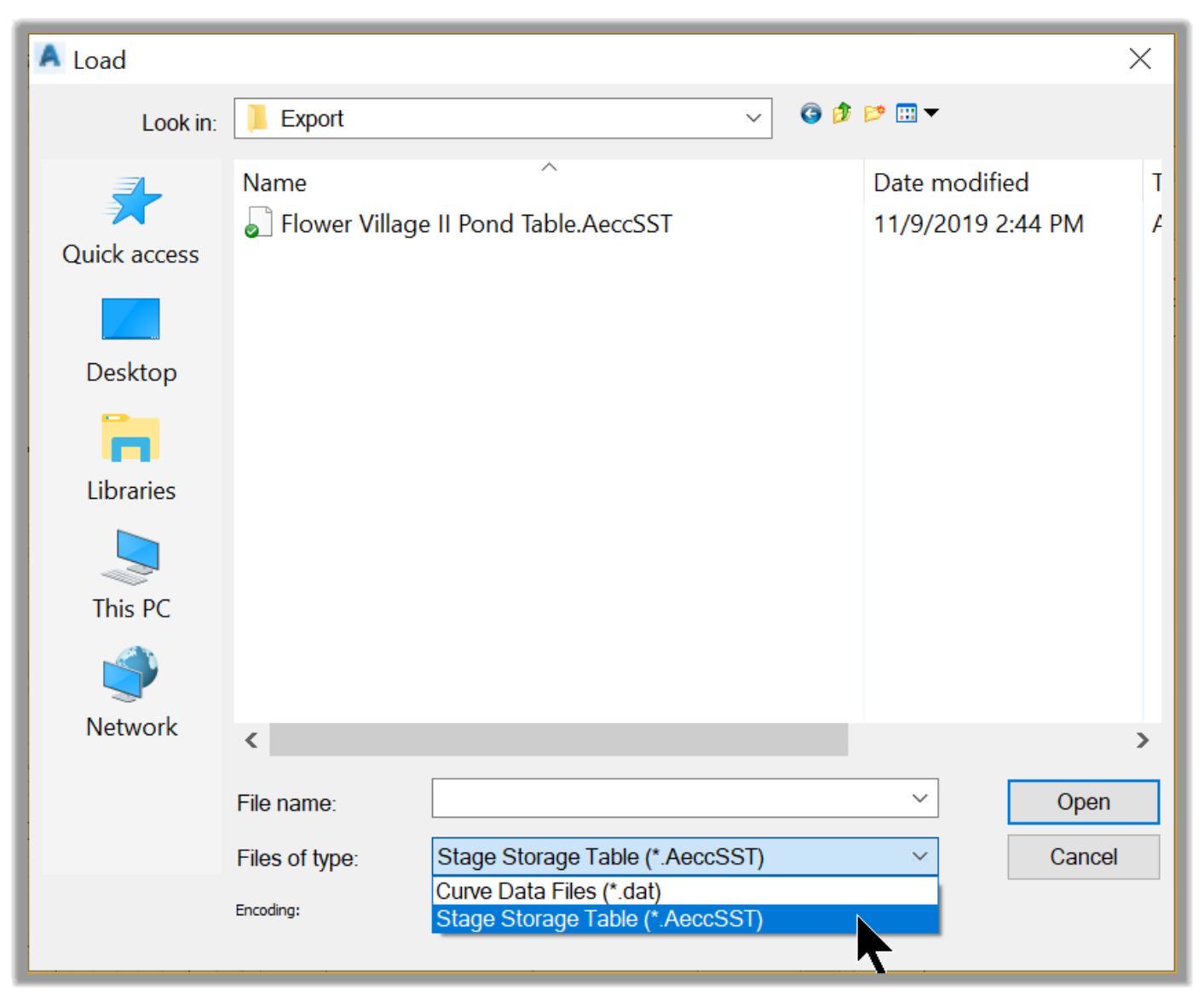
- Then, select the file and click on Open.
- The Stage Storage Curve is now automatically set, and we see a plot of the curve.
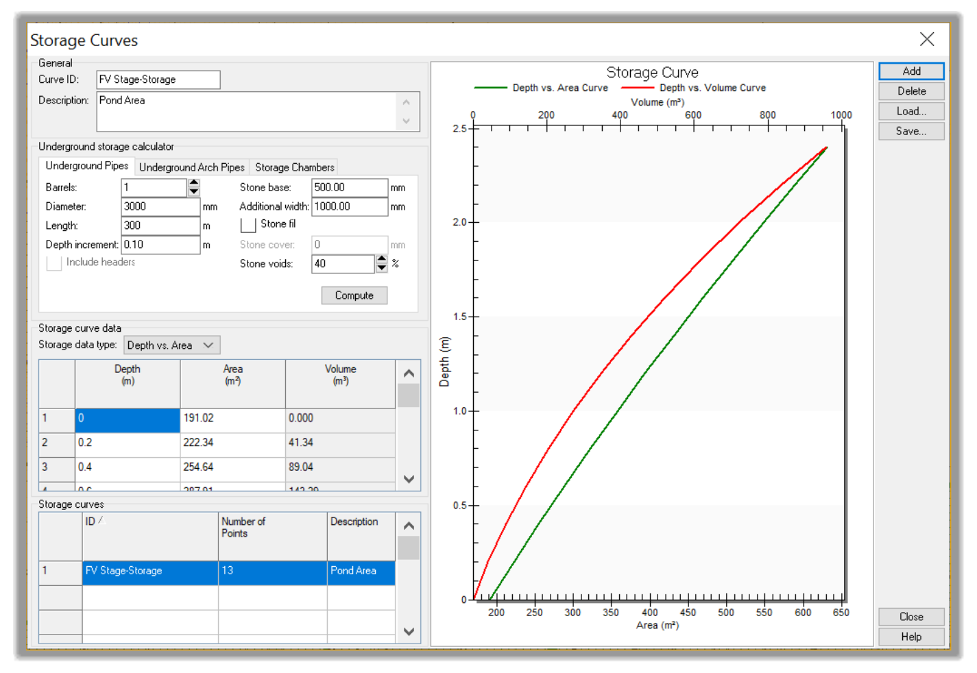
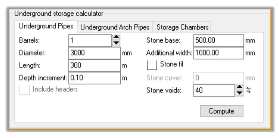
- Our pond is all set up. Before closing this window, we need to also mention that Storage nodes can be used to model Underground facilities.
- Now, let’s close both windows and return to the Data Tree.
- Click on Save
4.5.1.3 Inlets
Next, we need to design the inlets. As a reminder, manholes are represented as Junctions, while inlets represent catchbasins. For the inlets, we need to distinguish two types.
On Sag inlets: located at low points. They collect the most runoff water
On grade inlets: they are located on grade on the street. The collect part of the runoff water, while part continues to flow down the street to the next inlet. For these inlet types, we need to use what is called a bypass link. The bypass link will convey part of the runoff to the next catchment.
This picture illustrates the concept of On Sag, On Grade inlets, and bypass links.
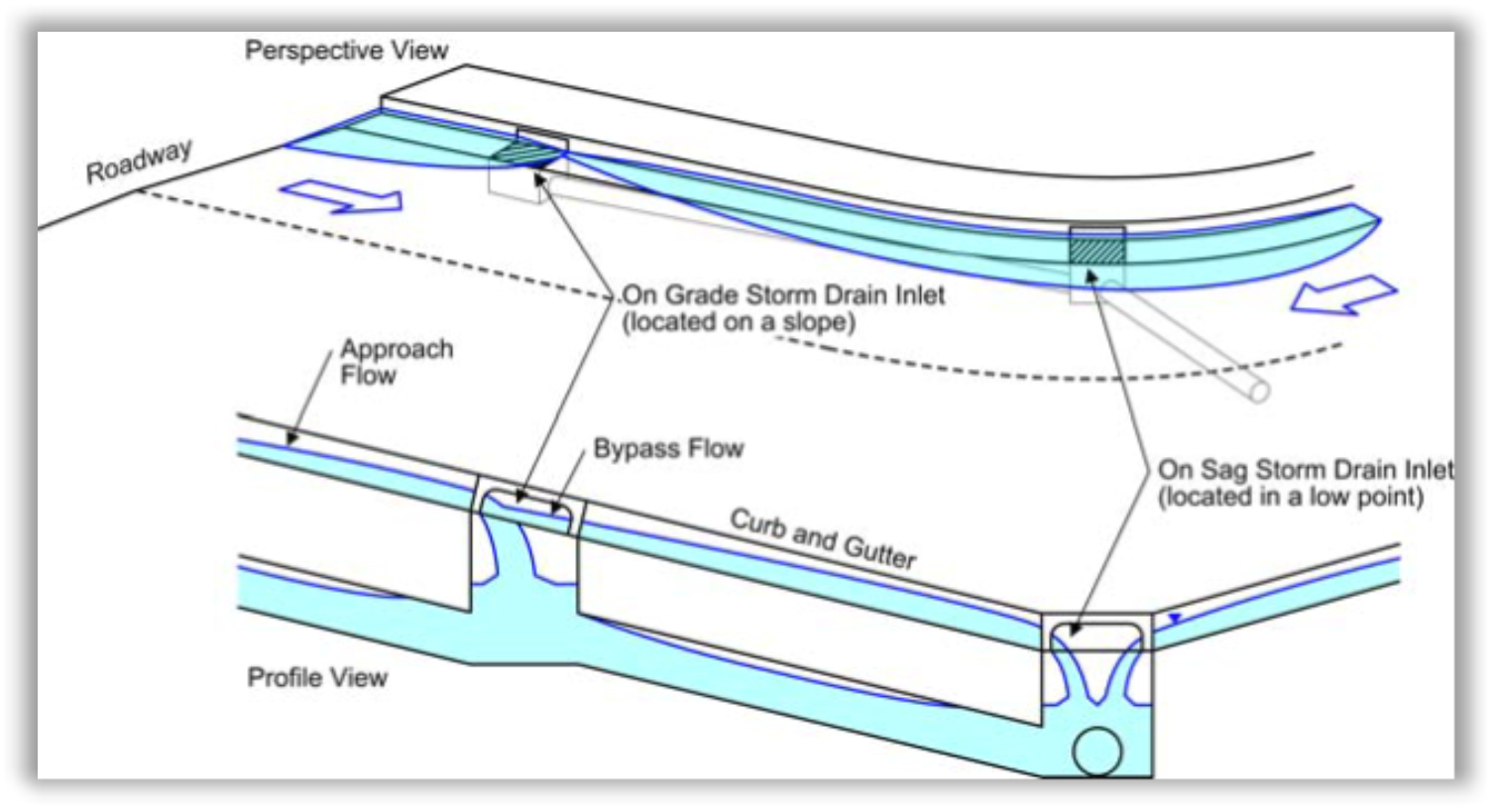
On Sag and On Grade inlets (from SSA User guide)
To design the inlets, we will set the right type for each inlet: On grade or On Sag. For On grade inlets, we also need to set a bypass link.
- Let’s work in the numerical order of the inlets, going from CB.101 to CB.111. In the plan view, double-click on CB.101.
- In the Inlets windows, we have the complete list of all inlets present in our project. We can see from the picture that this is exactly the Curb Grate Inlet type we chose in the part migration setup in Civil 3D. In addition, all the inlet data like rim elevation, sump elevations, etc. conform to the data in Civil 3D.
- Next, we need to set the following inlets as sag inlets: CB.101, CB.102, CB.103, CB.104, CB.105, CB.108. These are the inlet in low points. Meanwhile, CB.106, CB.107, CB.109, CB.110, and CB.111 will remain On Grade inlets since they are not in low points. Therefore, they will require bypass links. To set the type, just choose On Sag in the Inlet Location drop-down menu. Note how the Roadway/gutter bypass link option gets grayed out as we send the inlet to On Sag.
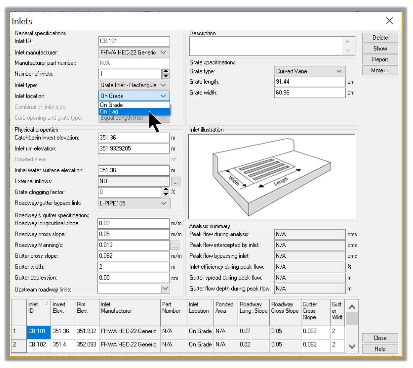
- We should now have all On Sag inlets sets. When changing the inlet location data, leave all the other data to their default values.
- Click Close to dismiss the Inlets window.
- Now, we need to:
Set the bypass links for the On Grade inlets.
And delete the bypass links for On Sag inlets. To do that, we only need to delete their outfalls. That will delete the link as well because, in SSA, links are always connected to a node. So, delete the following bypass links:
- So, let’s just delete the outfalls for the bypass: links for CB.101, CB.102, CB.103, CB.104, CB.105, CB.108.
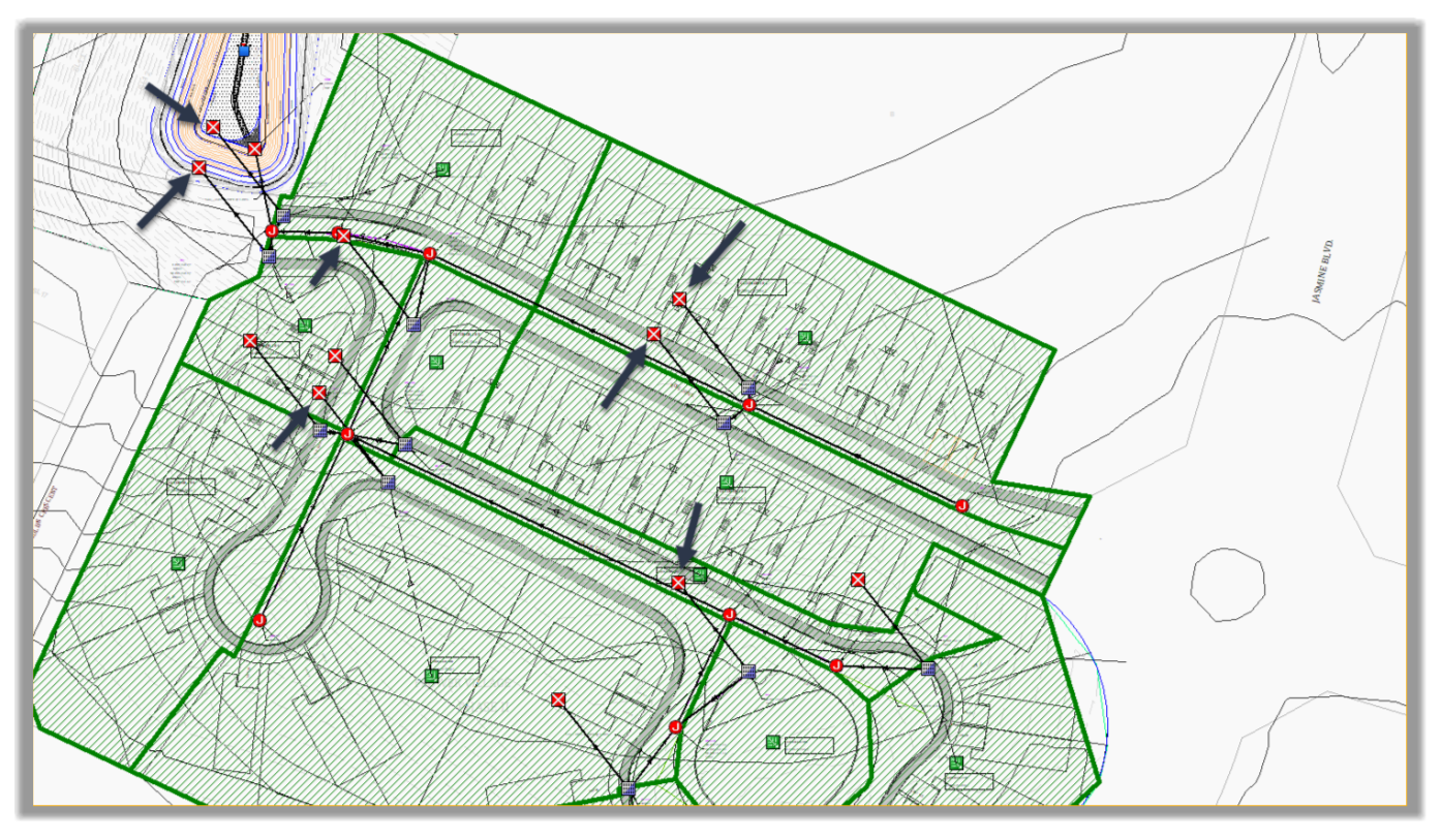
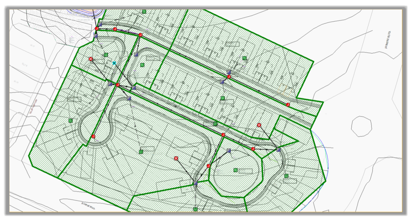
- The network should now look like this:
- Next, let’s set a bypass link, starting with CB.106.
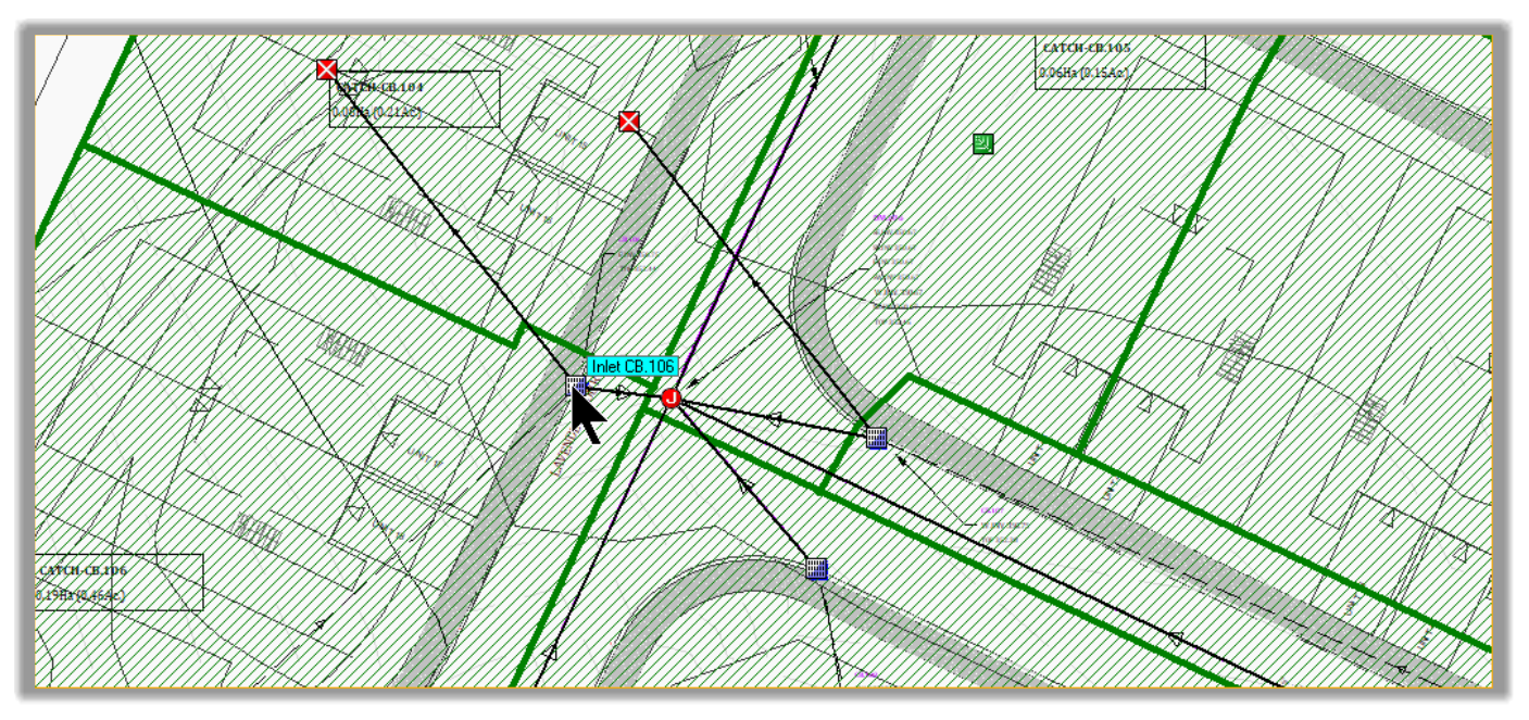
- CB.106 will be bypassed to CB.104.
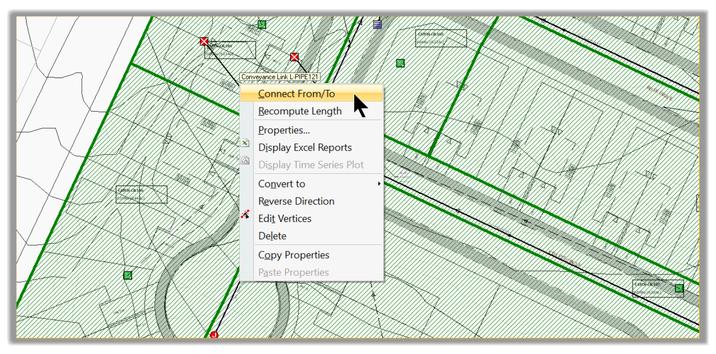
- Select the bypass link.
- Right-click and select Connect to
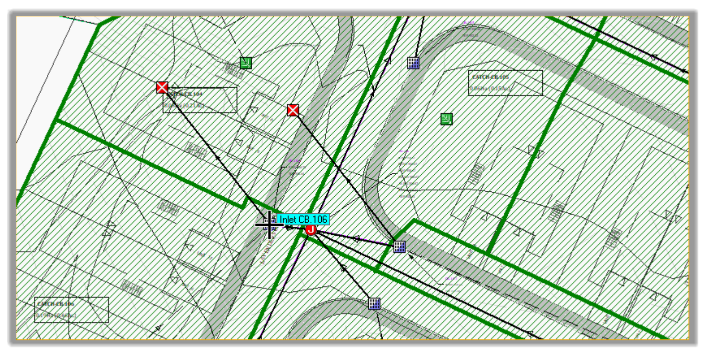
- Click on the origin inlet CB.106.
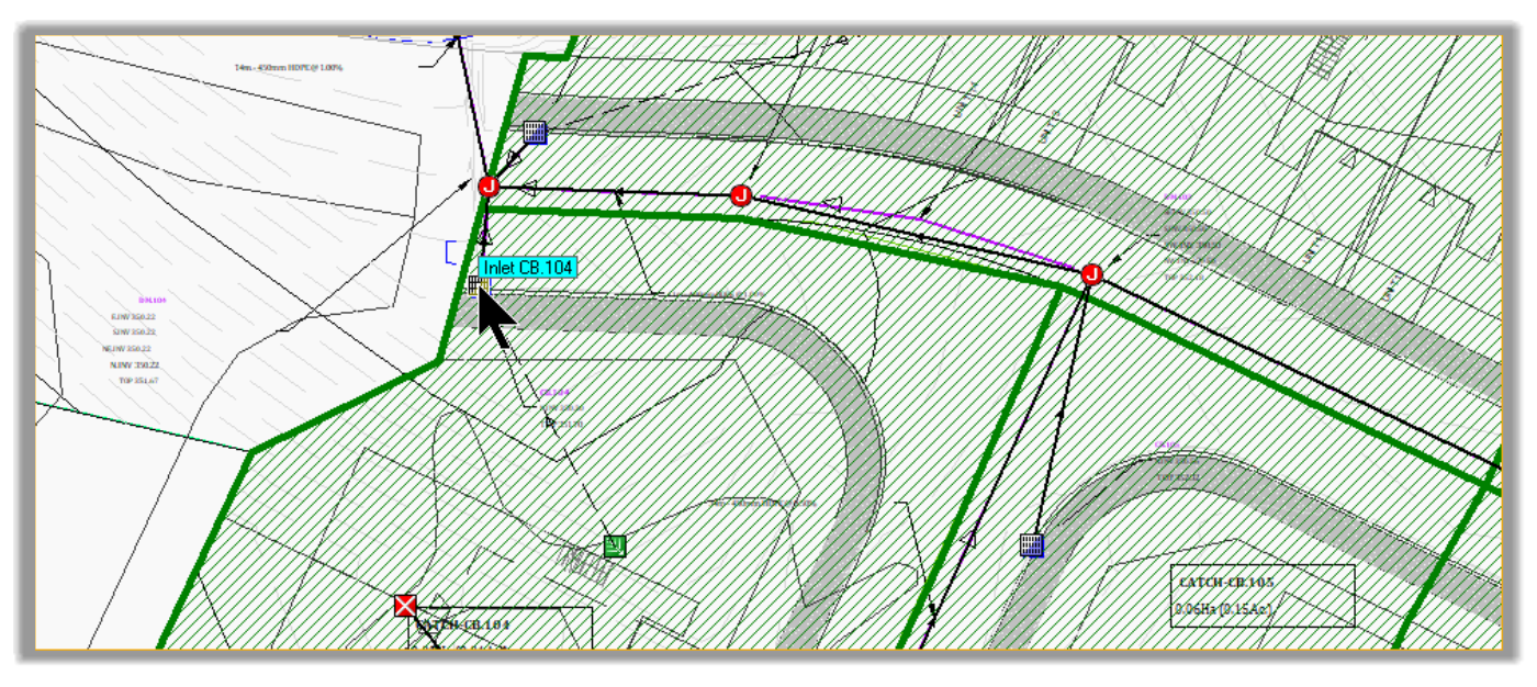
- Then on the destination inlet CB.104.
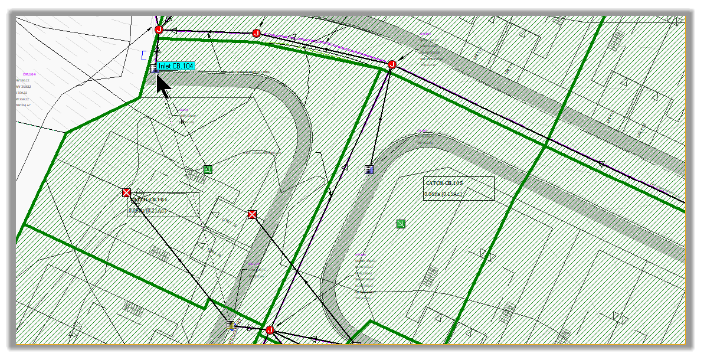
- The bypass link is now connected.
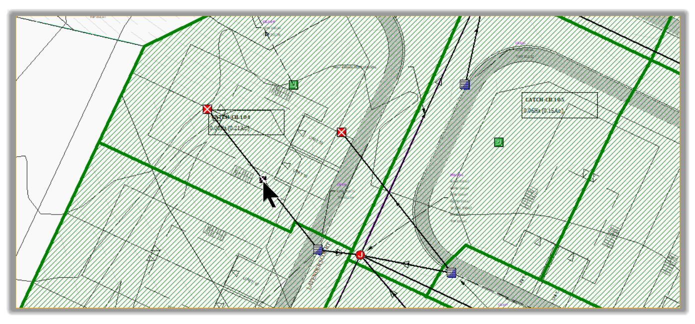
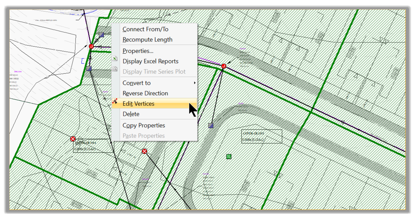
- Next, we need to edit to follow the curb line. Select the link.
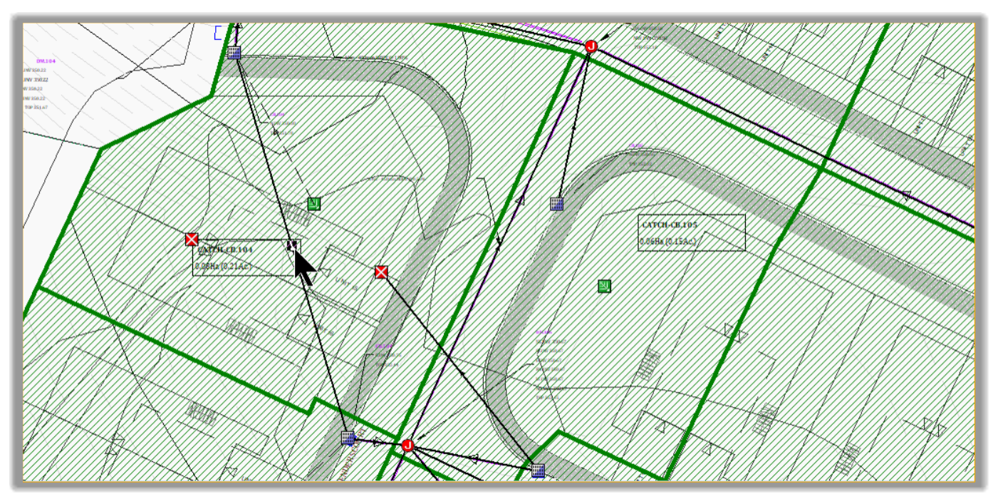
- Right-click and select Edit Vertices.
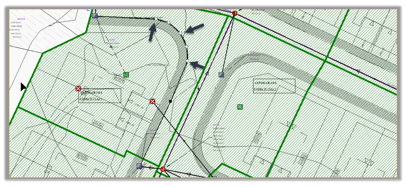
- The link is now in edition mode. To modify its course, we simply need to add or remove vertices. To add a vertex, right-click, and select add vertex.
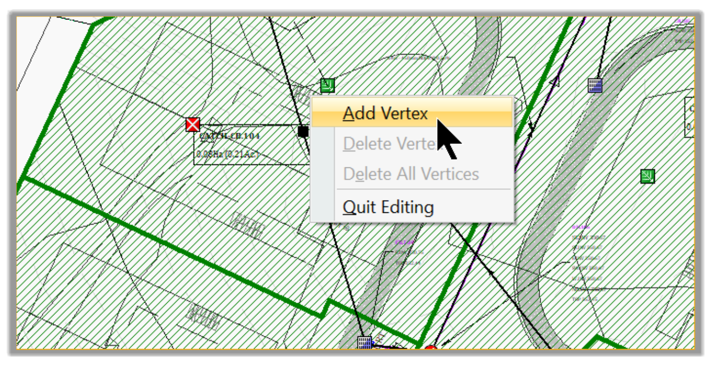
- Each time we run this command; you will notice a vertex is added.
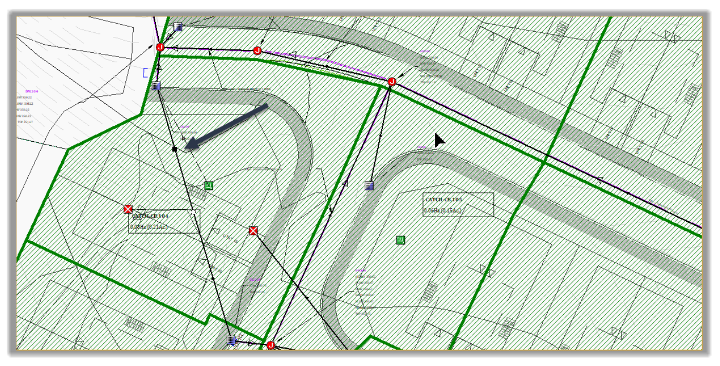
- Let’s keep adding vertices. Maybe 5 or 6.
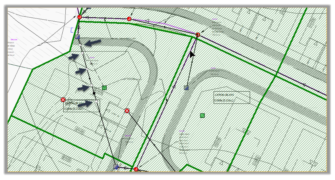
- Now, we can select the vertices and move them on the curb, to simulate the path of the bypassing runoff.
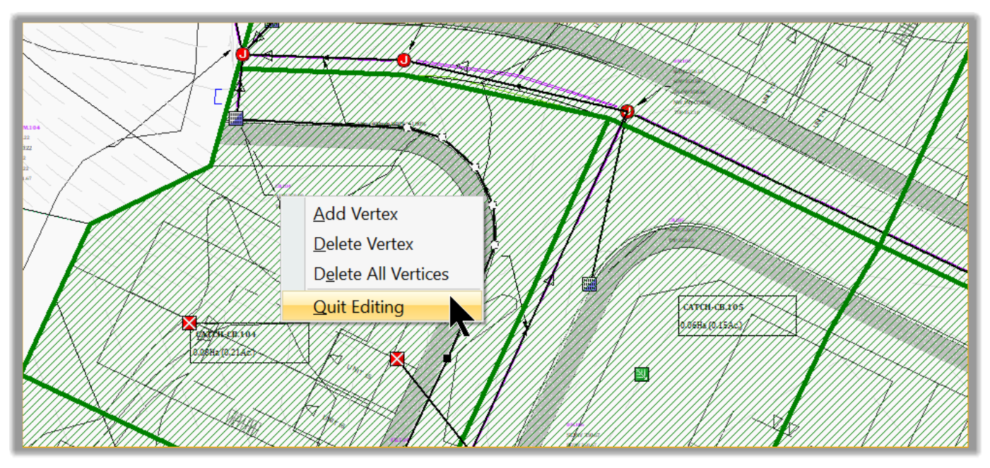
- If we are happy with the path, we can right-click and exit the edit mode by selecting Quit Editing.
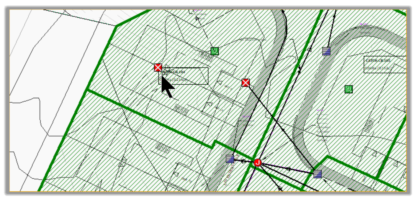
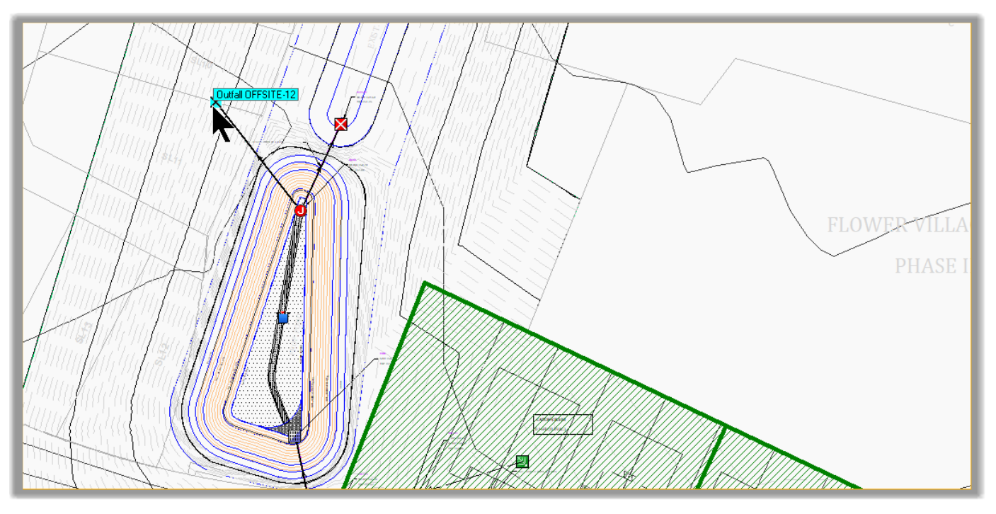
- Next, we need to delete the outfall where we have disconnected the bypass link. Select it and hit delete from the keyboard.
- Next, we need to repeat the same steps for the remaining On grade inlets: CB.107, CB.110, CB.111. They will have the following connections
CB.107 to CB.105
CB.110 to CB.107
CB.111 to CB.111
Don’t forget to delete the disregarded outfalls.
- That wraps up the site inlets.
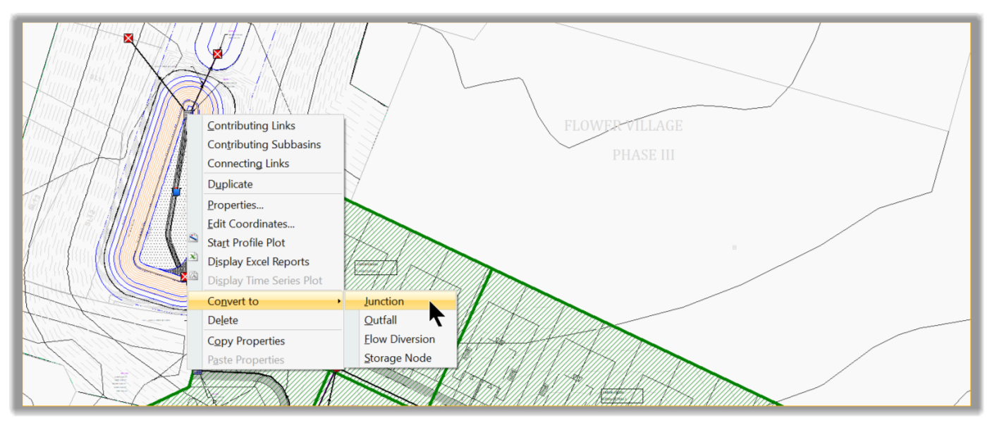
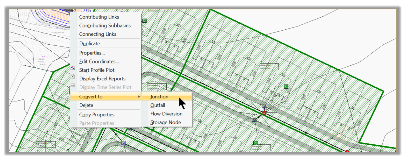
- Lastly, we need to set the last inlet, which is the outfall. For the outfall structure, we will just use a Junction, since we will have a weir and an orifice to regulate the flow. We will see later how to use them. To convert an inlet to Junction: select the inlet, right-click and select Convert to Junction.
- Do this for the pond incoming inlet, as well.
- Lastly, delete the unneeded bypass link for the Outfall structure. Select it and delete from the keyboard.
- We are now all set for the inlets. Next, we will set the outfall flow regulation devices: the orifice and weir.
- After the inlets in the node section, we should design the flow diversion structures. Since we don’t have any in this project, we will move to the next element, the outfalls.
Full Course and Free Book
-

SSA Stormwater Book and Practice Files
Course4.9 average rating (31 reviews)This pdf book includes the training manual and practice files for the advanced AutoCAD Civil 3D Storm and Sanitary Design course. This manual covers the skills needed to successfully design and analyze stormwater detention and sanitary sewer systems.
Purchase$19.99
-

Civil 3D Storm And Sanitary Analysis
Course4.9 average rating (14 reviews)In this Online Storm and Sanitary Analysis (SSA) training course, participants will learn and apply the tools offered by SSA, the Civil 3D companion software for stormwater management and design.
$99 / year