-
Get It
$19.99
$19.99SSA Stormwater Book and Practice Files
Storm and Sanitary Design Tutorial: pre-development vs post-development
Stormwater pre-development vs post-development
Product: Autodesk SSA | Subject: Storm and Sanitary Analysis
In this exercise, we will learn about stormwater pre-development vs the post-development conditions.
Pre-development conditions:
Before analyzing the storm detention model, we need to know the maximum allowable flow rate. This value should be equal or less than the pre-development conditions. To determine that value, we need to run a pre-development model.
To model the pre-development flow rates:
- Open the file 05.03-DETENTION-PRE-DEVELOPMENT.spf or keep working with the previous file if you are following along.
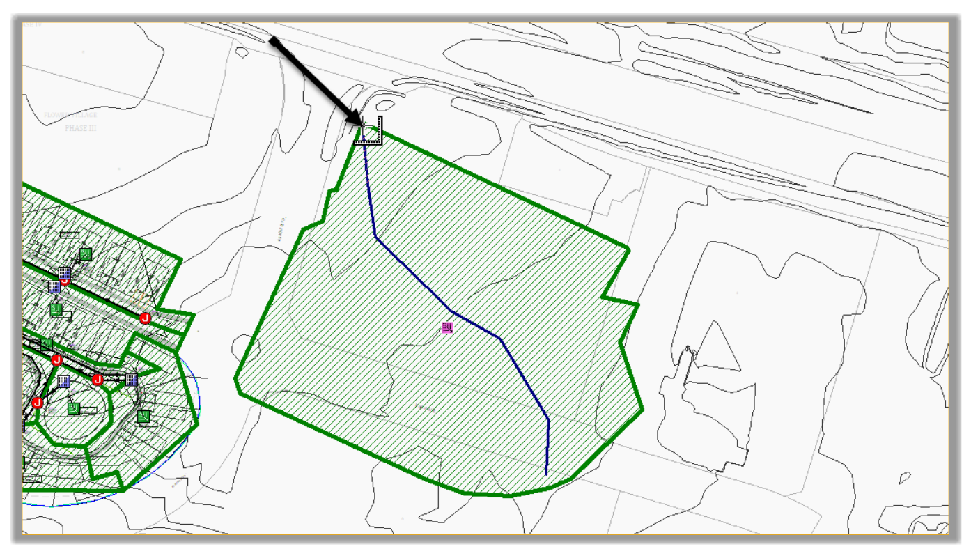
- First, we need to create a catchment for the existing site. Run the catchment creation command from the toolbar.
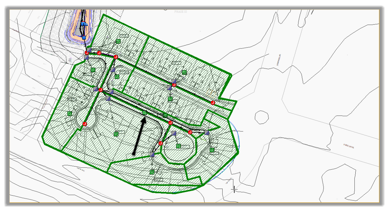
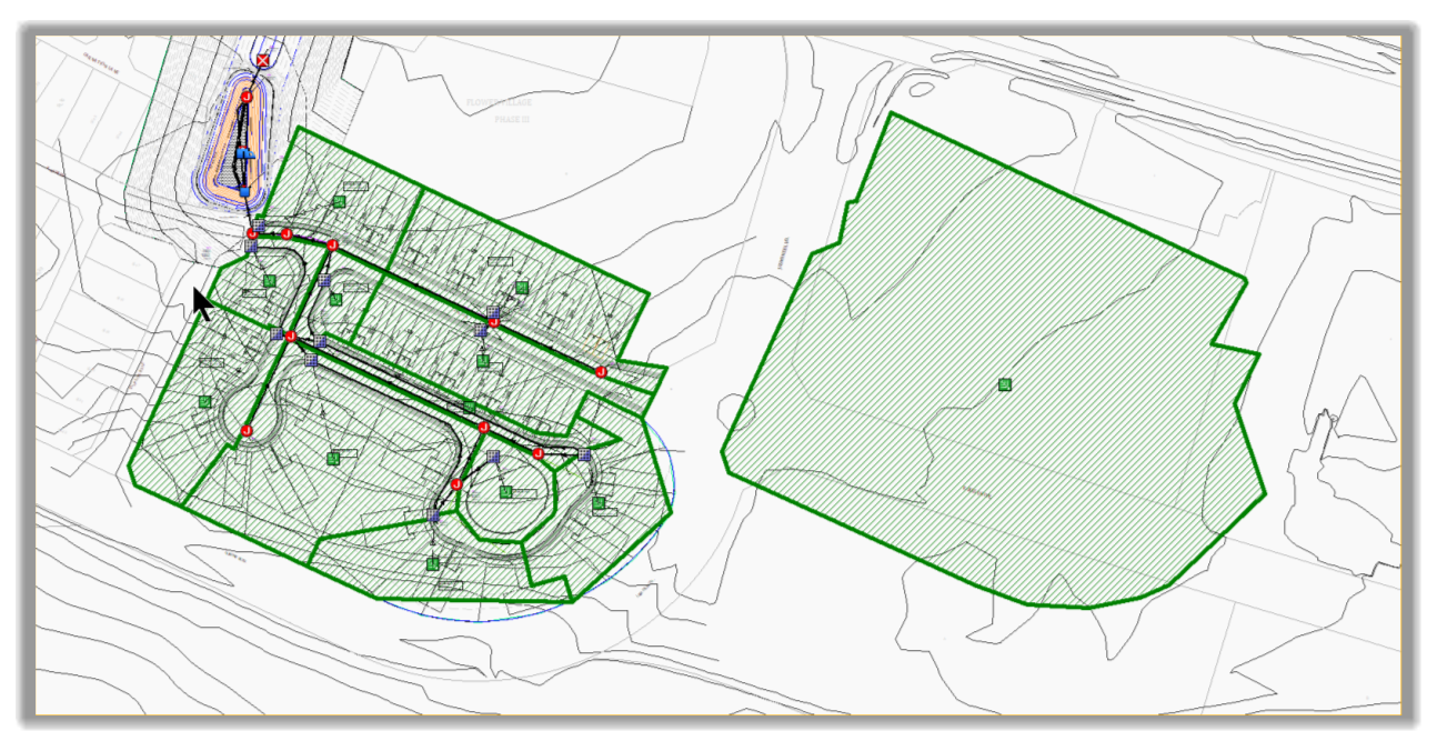
- Then, draw the catchment by following the perimeter of the existing site. When you get close to the start point, double-click to close the catchment.
- Press ESC.
- The new catchment is now created.
- Select the catchment and move it to the side to make it easier to work with.
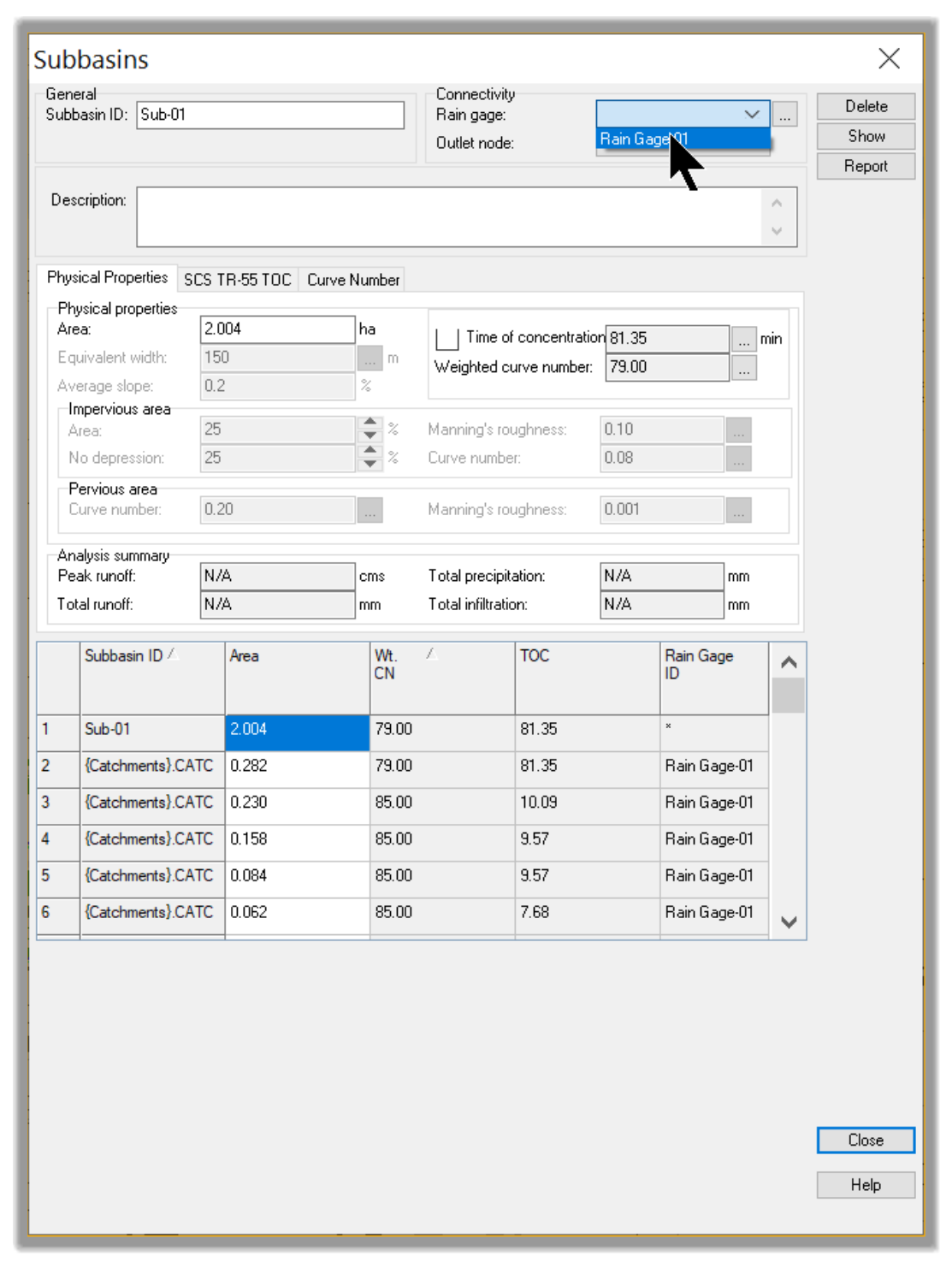
- Double-click to open its properties. The pre-development area is already calculated and comes in at 2ha or 5ac as expected
- Now, switch to the SCS TR-55 table.
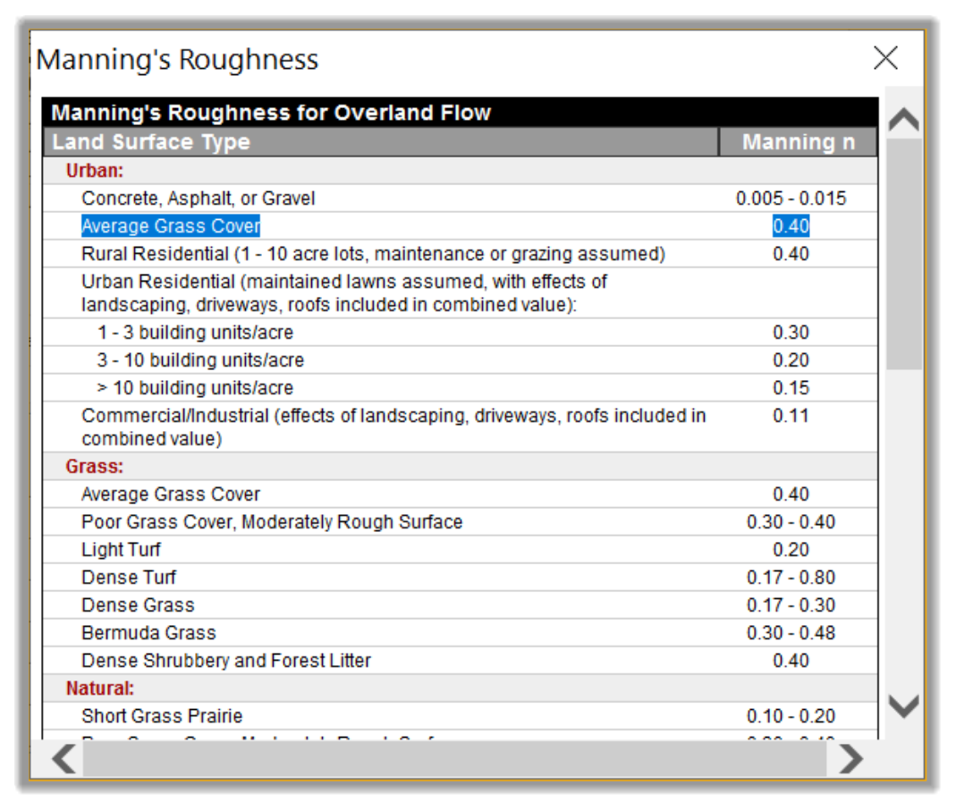
- Click on the Manning’s roughness line ellipsis.
- Our current pre-development site is an average grass cover. So, let’s choose 0.40 for manning roughness
-
Click on the Flow length line ellipsis
 .
. - Draw a line from the furthest point to the approximate location of the pre-development site outlet and double-click.
- The flow length comes in at 191m or 625ft. Because we are in pre-development conditions with bare ground cover, let’s put the Sheet flow length at 100m or 300ft. The rest will be Shallow Concentrated Flow.
- Switch to the Shallow Concentrated Flow tab and input 91m or 325ft. Use 2% for slope and Unpaved surface type.
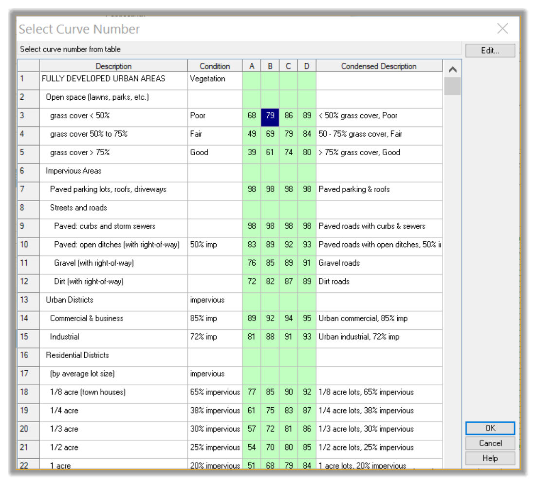
- Next, let's switch to the Curve number tab. Click on the ellipsis in the first line. In the Select Curve Number table, select grass cover less than 50% and click OK.
- Before we close the Subbasins window, we need to assign the same rain gage used by the post-development subbasins to the newly created pre-development catchment.
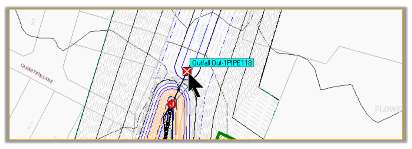
- Before we analyze the pre-development flow rate, we also need to assign an outlet to the pre-development catchment Click on the Outfall command on the toolbar.
- Then click to insert the outfall at its approximate location.
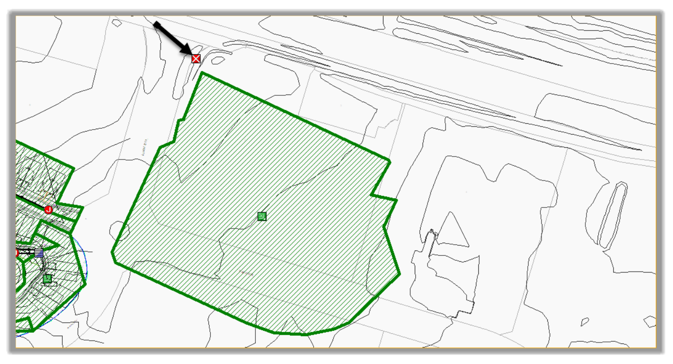
- Hit Escape.
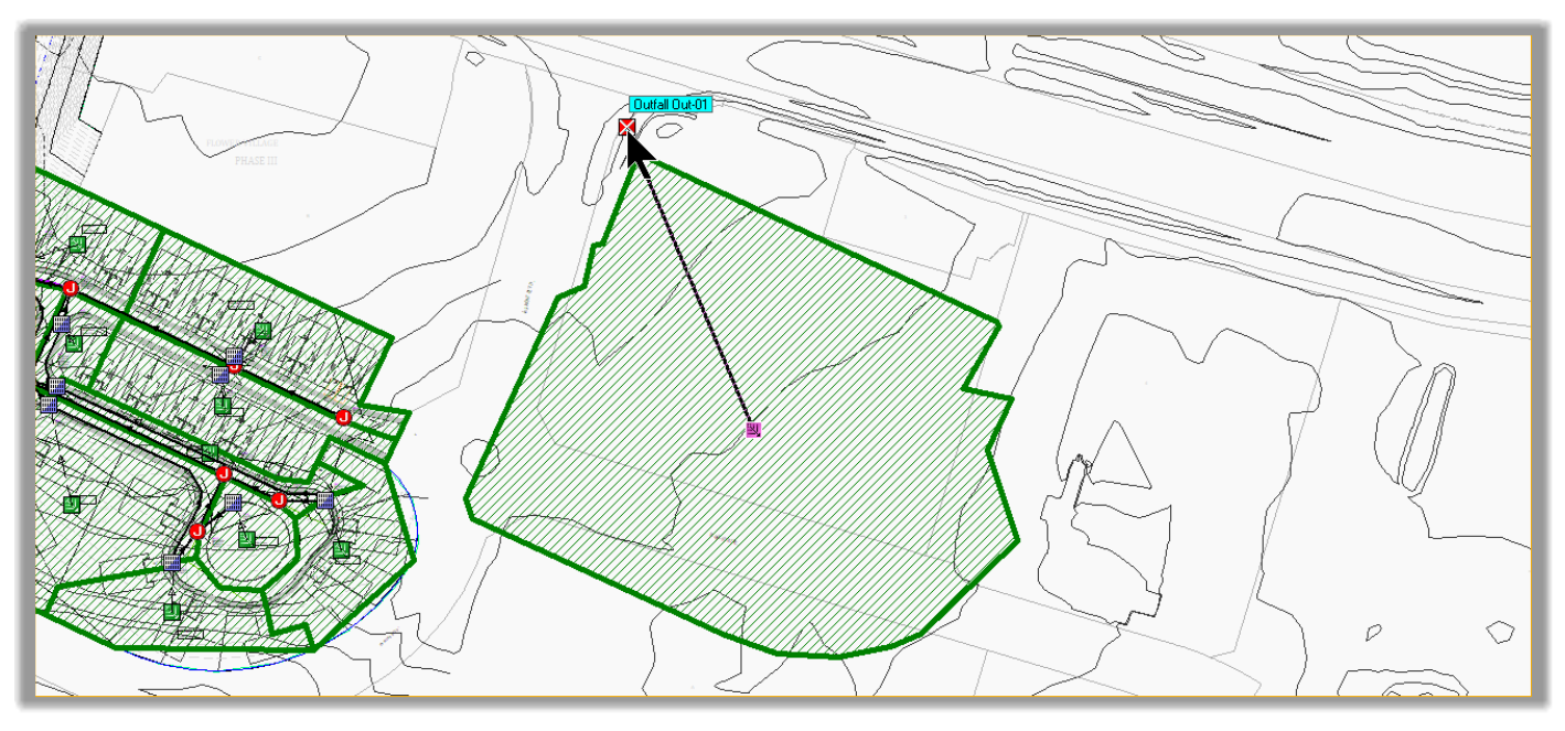
- Next, we need to connect the catchment to the outfall. Select it, right-click and choose Connect To
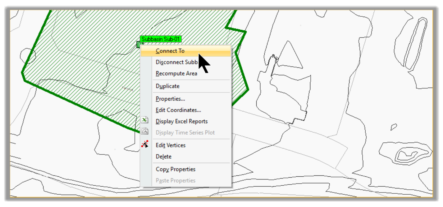
- Choose the pre-development Outfall for connection
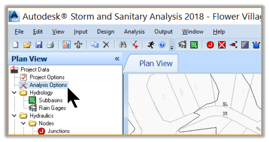
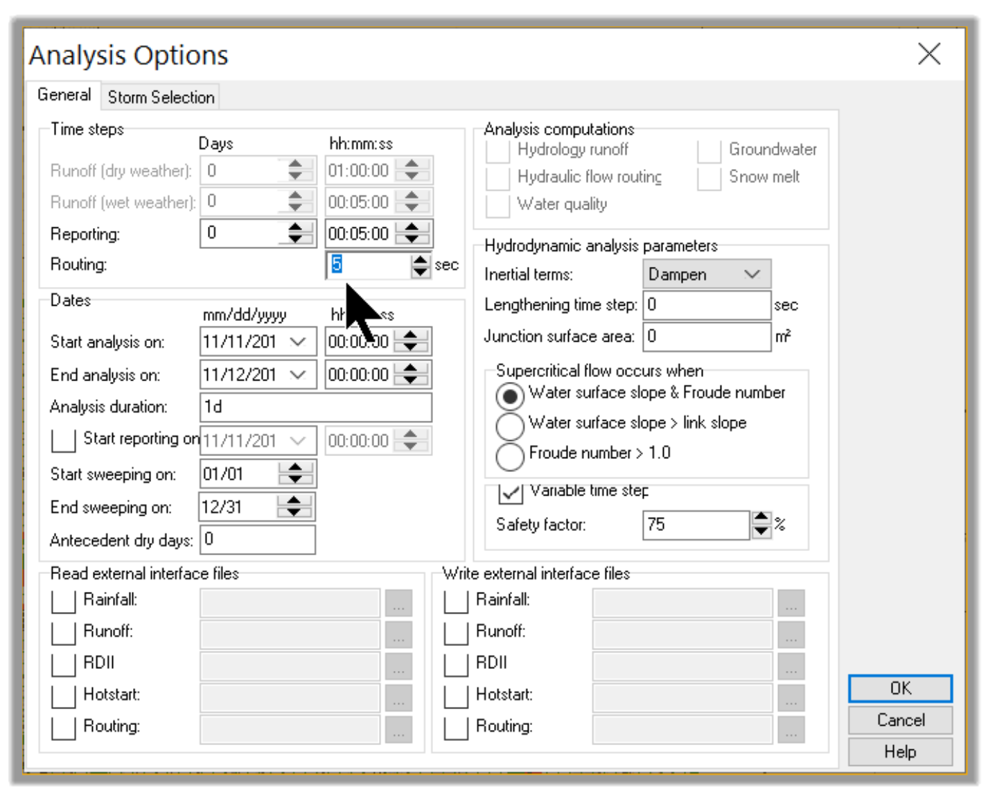
- Before running the analysis, we need to set the duration of the analysis. Remember that this file comes from the Storm Sewers analysis, which were analyzed only for the 60 minutes duration since that’s all was needed. Let’s change that. Double-click on Analysis Options.
- In the Analysis Options window, change the End Analysis on to the next day, in order to have at least 24-hours.
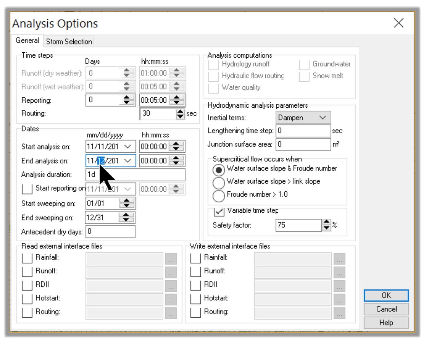
- Let’s also adjust the routing time step. We need the shortest time step possible to have the best results. So, let’s set the time step to 5 seconds instead of 30.
-
Now, we are all set to run the model for the required frequency and duration. Click on Analysis
 to run the model.
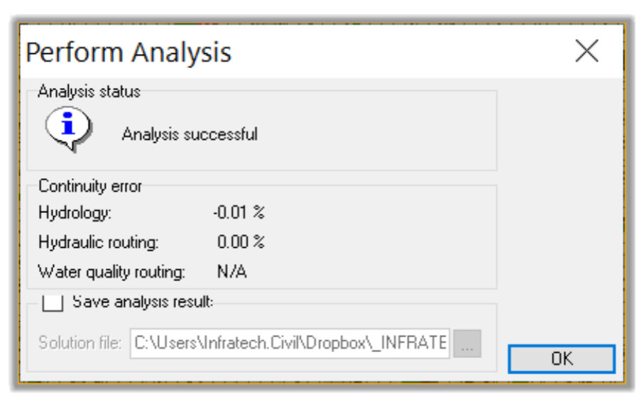
- Our model analysis is successful once again. Optionally, we can save the results of this analysis. We will not do that in this instance.
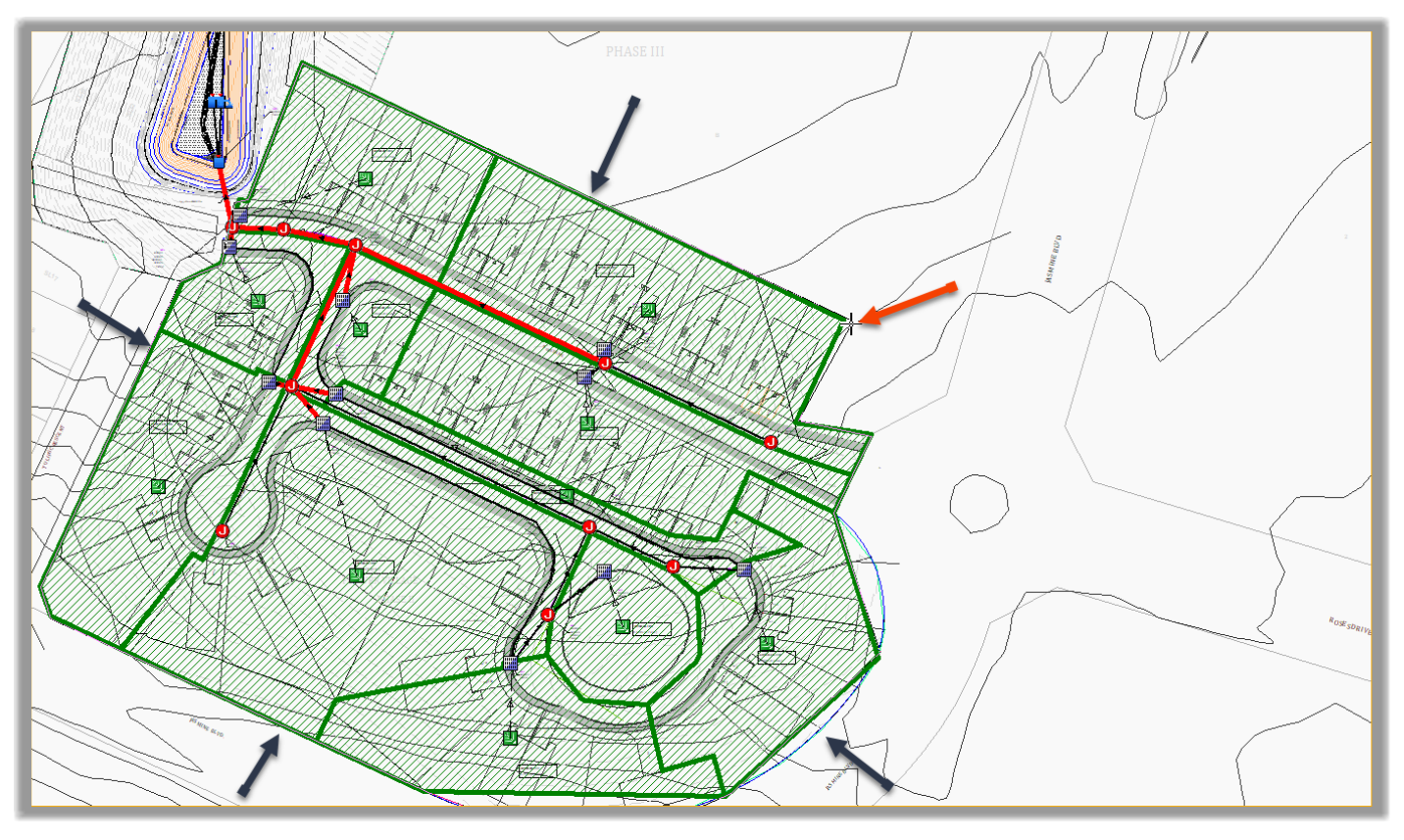
- In the plan, we can notice that the post-development is showing that the pipes (red lines) are surcharged. The pipes being surcharged should not be a concern. That’s expected for the 100-year storm event.
- For now, click on OK to close the Perform Analysis window
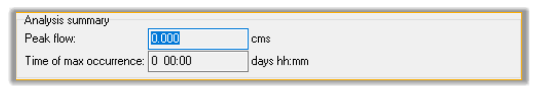
- Next, in the plan view, double-click on the outfall. In the Outfalls window, we can see that the Peak flow in pre-development conditions is 0.11cms or 0.48cfs. This will be the maximum off-site flow of the post-development.
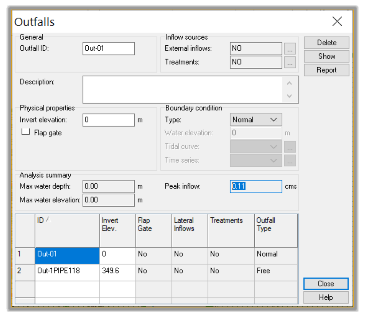
- Close the Outfalls window.
- Next, we will analyze and compare the post-development to the pre-development flow.
5.3 Adjusting Post-development to match pre-development flow.
Now that we know the pre-development peak flow, we can turn our attention to the post-development flows.
- Open the practice file containing the pre-development conditions 05.04-DETENTION-Adjustment.spf or keep working with the current one.
- Let’s run the model
 one more time to update the results.
 - The first thing we notice is that the pipes are surcharged. This is acceptable for the 100-year flood, as long as we avoid overtopping the nodes. So, we don’t need to worry about it.
- The second thing we need is to analyze the peak site outflow. To check it, we need to double-click on the post-development Outfall node.
- We can see that the Peak inflow is way more than the maximum allowable of 0.11cms or 3.88cfs.
- Usually there are two challenges we need to solve: flooding at the nodes and the site outflow exceeding the allowable rate.
- Let’s see how to fix excessive peak flows. First, we need to understand where they are coming from. If you double-click on the Orifice and Weir, you will notice that most of the flow is coming from the weir.
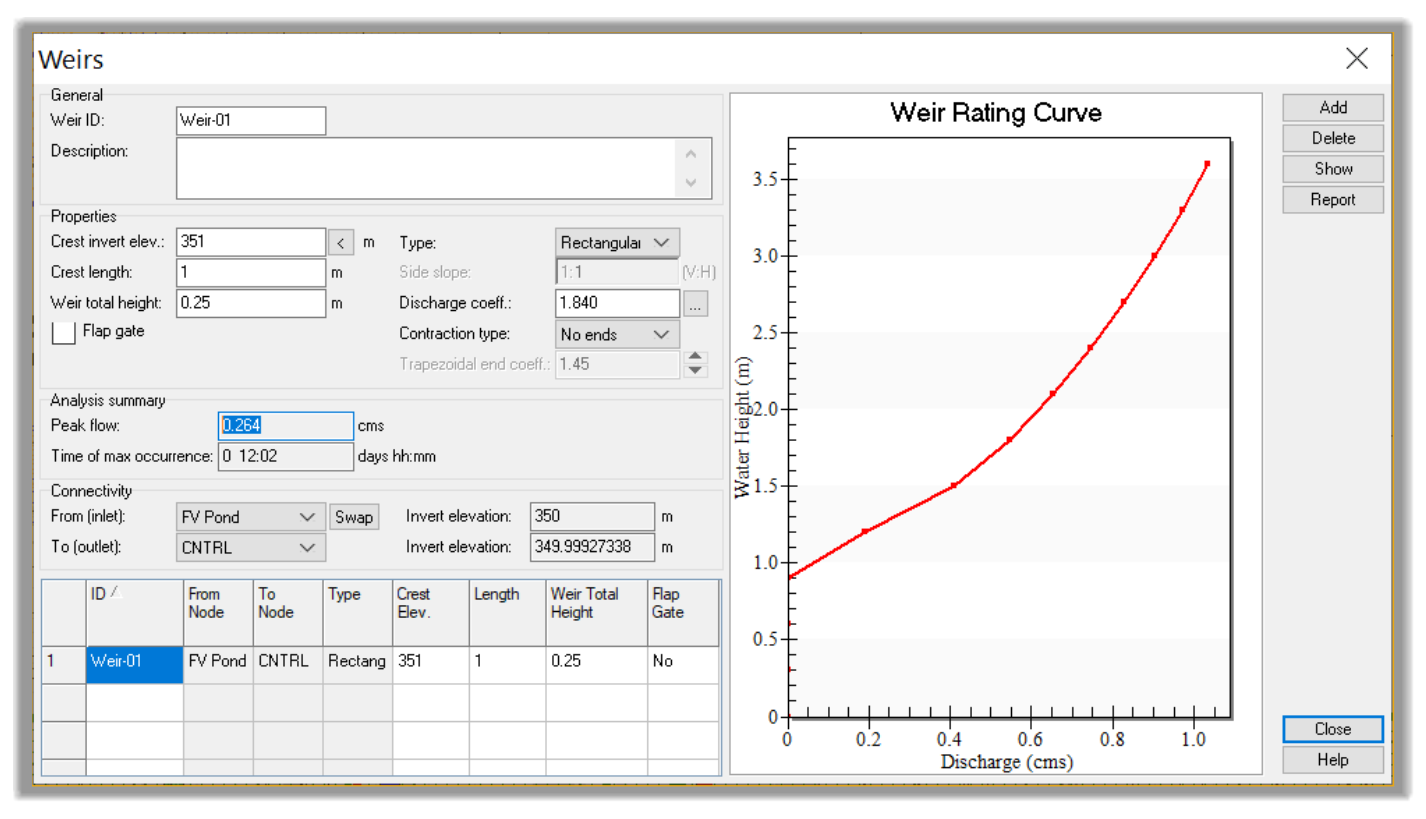
- So, we need to raise it so that no flow goes through the weir during the 100-year. We need to route all the flow through the orifice for the 100-year. The weir will only kick in for flows above the 100-year flood.
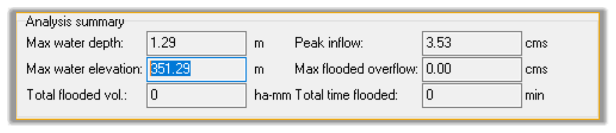
- To find the current maximum elevation, double-click on the pond element.
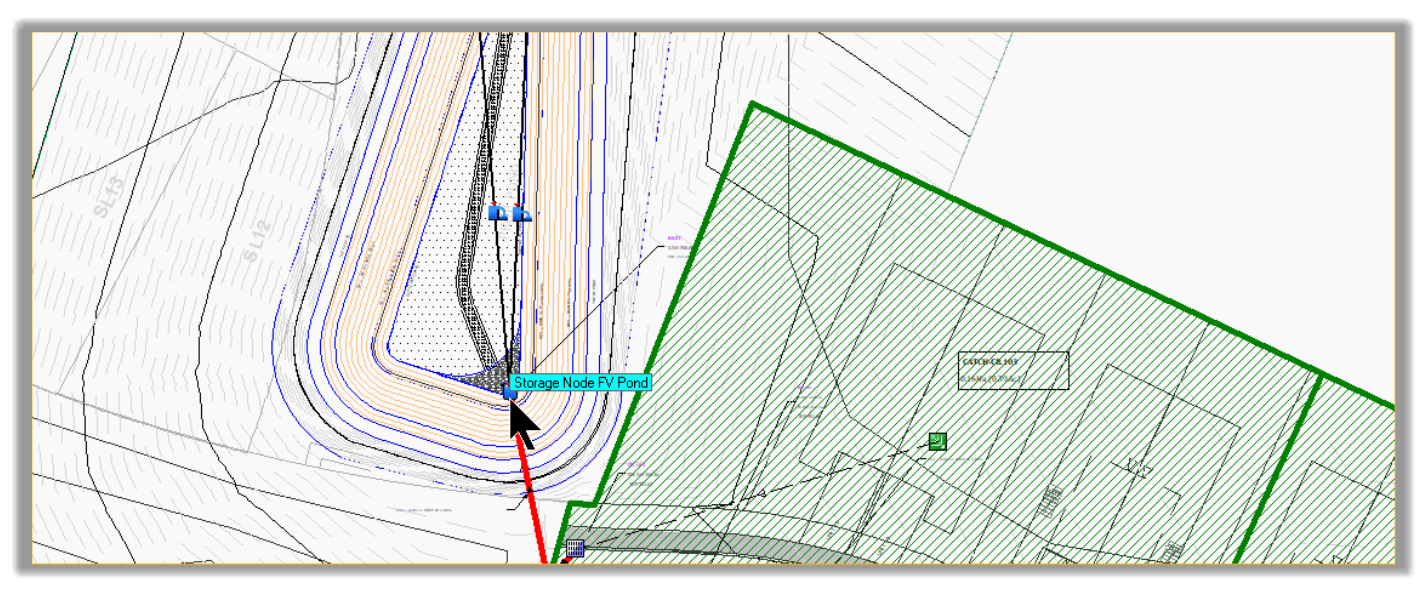
- We can see that the current maximum elevation reached is 351.23m or 1152.50ft.
- Now let’s set the weir at a higher elevation to avoid any flow through it. Let’s say 352.5. This is an arbitrary value. We will have the final value later. Double-click the weir and set its elevat
-
Let’s run the model
 one more time. If we check back the weir information, there is no flow. That fixes the weir for now.
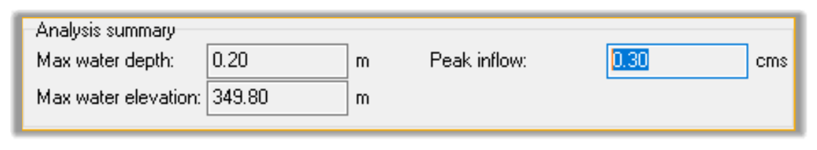
- If we check the site outflow, through the outfall, we have now only 0.05cms or 1.8cfs, which is very little. We need to increase the orifice to get the flow close to the allowable 0.11cms or 3.88cfs. So, let’s increase the size of the orifice.
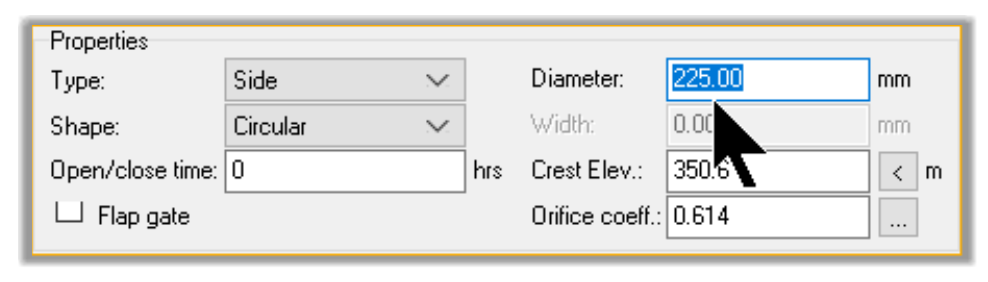
- Double-click on the orifice and change the size from 150mm or 6in to 225mm or 9in. This is an orifice; it doesn’t need to be a standard pipe diameter size.
- Now, let’s check the outflow. If we double-click on the outfall, we can see that the flow is now 0.09cms or 3.50cfs. That is close enough to the maximum 0.11cms or 3.88cfs allowed.
- While we are here, let’s make sure we increase the pipe size going out of the pond to at least one size bigger than the incoming pipe. We will need that size for floods above the 100-year. So, let’s set it to say 750mm or 30in.
- We have now sized the orifice to meet peak outflow requirement.
- Close the Conveyance Links window.
- We should note that we don’t have flooding at the nodes, so we are all set. Typically when we have flooding at a node, the solution would be a combination of:
Increasing the size or slope of the outgoing pipes to allow more outflow.
Decreasing the size or slope of the incoming pipes to throttle incoming flows at the node.
Increasing the size of the pond or making it bigger.
- How make these adjustments and balance the system is where the engineer’s judgment comes into play and designing becomes an art.
Full Course and Free Book
-

SSA Stormwater Book and Practice Files
Course4.9 average rating (31 reviews)This pdf book includes the training manual and practice files for the advanced AutoCAD Civil 3D Storm and Sanitary Design course. This manual covers the skills needed to successfully design and analyze stormwater detention and sanitary sewer systems.
Purchase$19.99
-

Civil 3D Storm And Sanitary Analysis
Course4.9 average rating (14 reviews)In this Online Storm and Sanitary Analysis (SSA) training course, participants will learn and apply the tools offered by SSA, the Civil 3D companion software for stormwater management and design.
$99 / year