Civil 3D Survey Databases
Field to Finish Survey Databases
Product: Autodesk Civil 3D | Subject: Surveying with Civil 3D
In this exercise, we will learn about Civil 3D Survey Databases
3.4.1 Survey Databases
3.4.1.1 Survey Database Settings
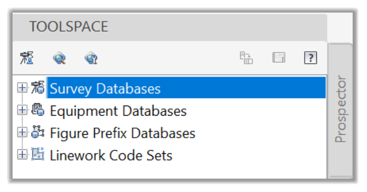
The Survey Database is where most of the field survey information resides, including field measurements, setups, control points, and much more.
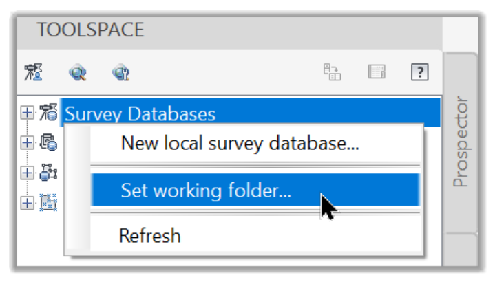
- First, in the Survey Database section, we need to be aware of a few settings. If we right-click on it, we can Create a New Database, Set the working Folder, or Refresh the existing databases.
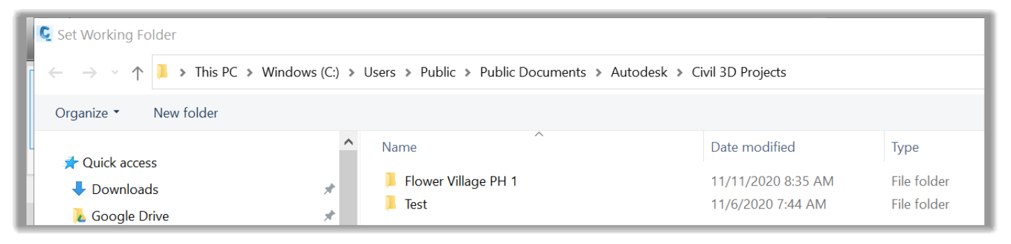
- It is essential to mention here is that we should always keep in mind the path of the Current Working folder databases. For example, the main reason for this is that a Survey database cannot be renamed or deleted from Civil 3D. To do so, we need to go to the physical path of the database. For example, in this case, if we click on Select the working folder, we are taken to the current working folder where we see directories for each of the databases we have created so far.
- We can select any folder on our computer or office network to manage our projects and databases. At any time, we can deactivate the database in Civil 3D and go to the working folder to edit its files if needed, even though it is not usually recommended to mess with databases outside of Civil 3D to protect the integrity of the data. Ideally, only the survey managers of your office should be able to edit the Survey Working folder. A typical workflow is to connect to the database, insert the needed information into the Civil 3D drawing. We can then make all the required changes in the picture without changing the original data.
- Next, we need to set the current working database. To do that, we can right-click on any of the existing databases (mostly past or present projects) and click on Open for Edit.
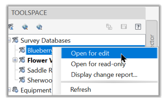
- Once the survey database is Opened for Edit, it will be locked for all other users. This is why it is recommended just to open the database, insert the data we need in the drawing, and free up the database for other users. When opened, we can right-click on the database and access more options, including:
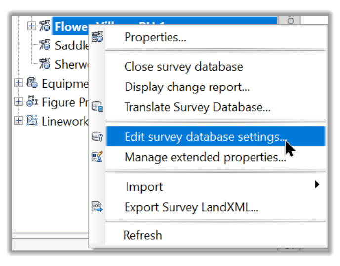
Accessing the database properties
Closing the database
Displaying reports
Translating the database. This would be useful when going from local to referenced coordinates.
Editing the survey database settings like the Units, precisions, etc., as we have seen earlier. The Unit settings are particularly important, and a distinction should be made between two imperial foot. US users should use the US Foot units in most cases. Other users should mostly use Metric units or International foot when required.
Managing extended properties
Importing additional survey data and files in the database.
Exporting data from the database to landxml format files
And refreshing the Survey databases.
3.4.1.2 Import Events
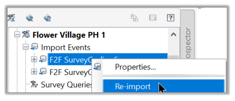
The Import Events section provides us a listing of the instances when data was imported into the Survey Database.
- We can also use this section to import data by right-clicking and running the Import Survey Data command. This is equivalent to the same command we run earlier when Importing the Civil 3D data.
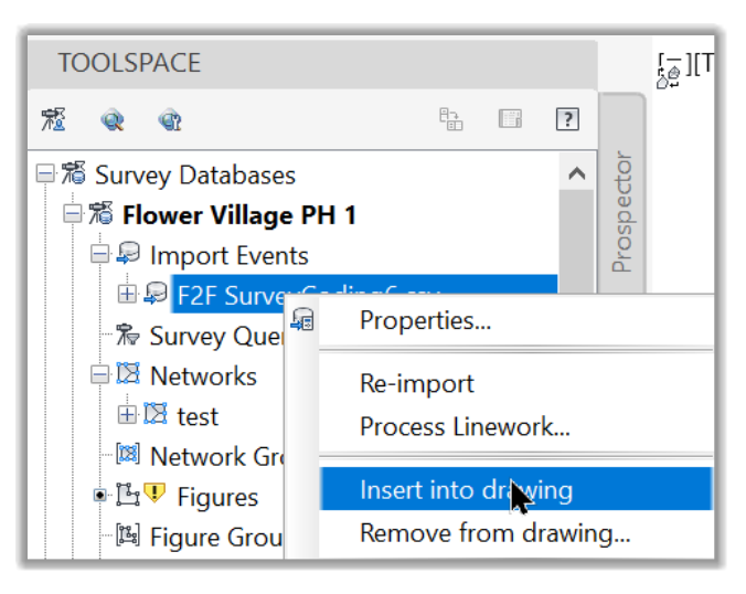
- In addition, if a survey file was modified externally and we were notified of the changes, we can re-import the file by simply clicking on Re-import on the name of the import event.
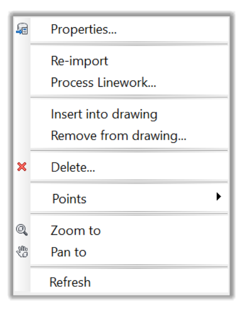
- Finally, we can also perform different operations from an import event such as processing linework, inserting data from a database into the drawing, deleting the event, editing, inserting or removing points, zoom, pan, or refreshing the event.
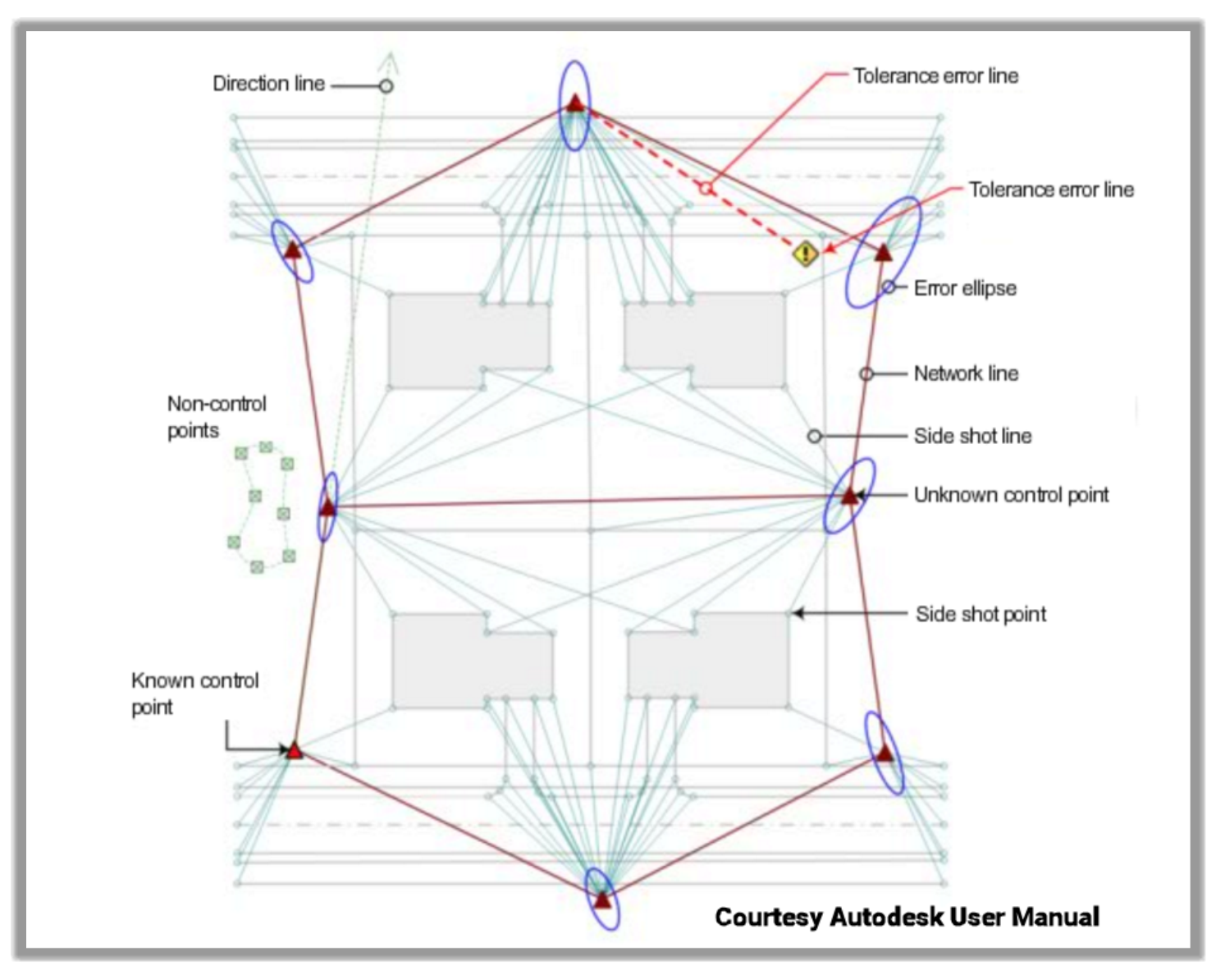
3.4.1.3 Survey Networks
Next, in the database tree, we have the Network section. As we have mentioned earlier, in Civil 3D, a survey network is a data set with a connection between them. They are usually part of a single survey operation and share an equipment setup, observed backsights, foresights, control points, etc.
Only the data that are part of the same network can be analyzed to perform specific survey operations such as traverse analysis, closures, etc.
By right-clicking on Networks, we can,
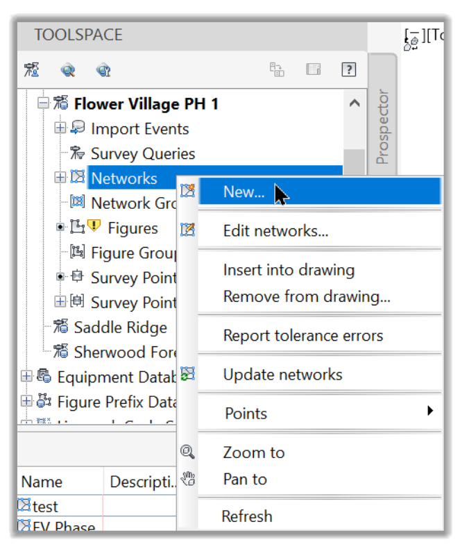
- Create a New network
- Edit an existing network
- Insert or Remove network data in the drawing
- Report tolerance errors
- Update networks
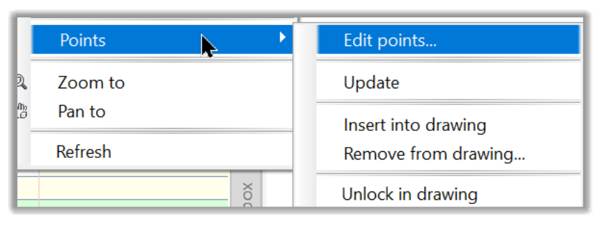
- Edit, Update, Insert, Remove, or Unlock survey points in the drawing.
- And finally, Zoom, Pan, or Refresh a network.
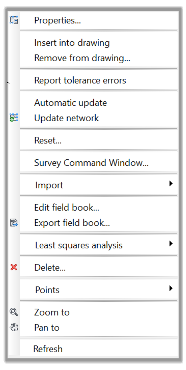
- Furthermore, network-specific operations can be performed by right-clicking on the specific network. For example, if we right-click on the Phase 1 Initial network, all the listed operations will be related to this particular network.
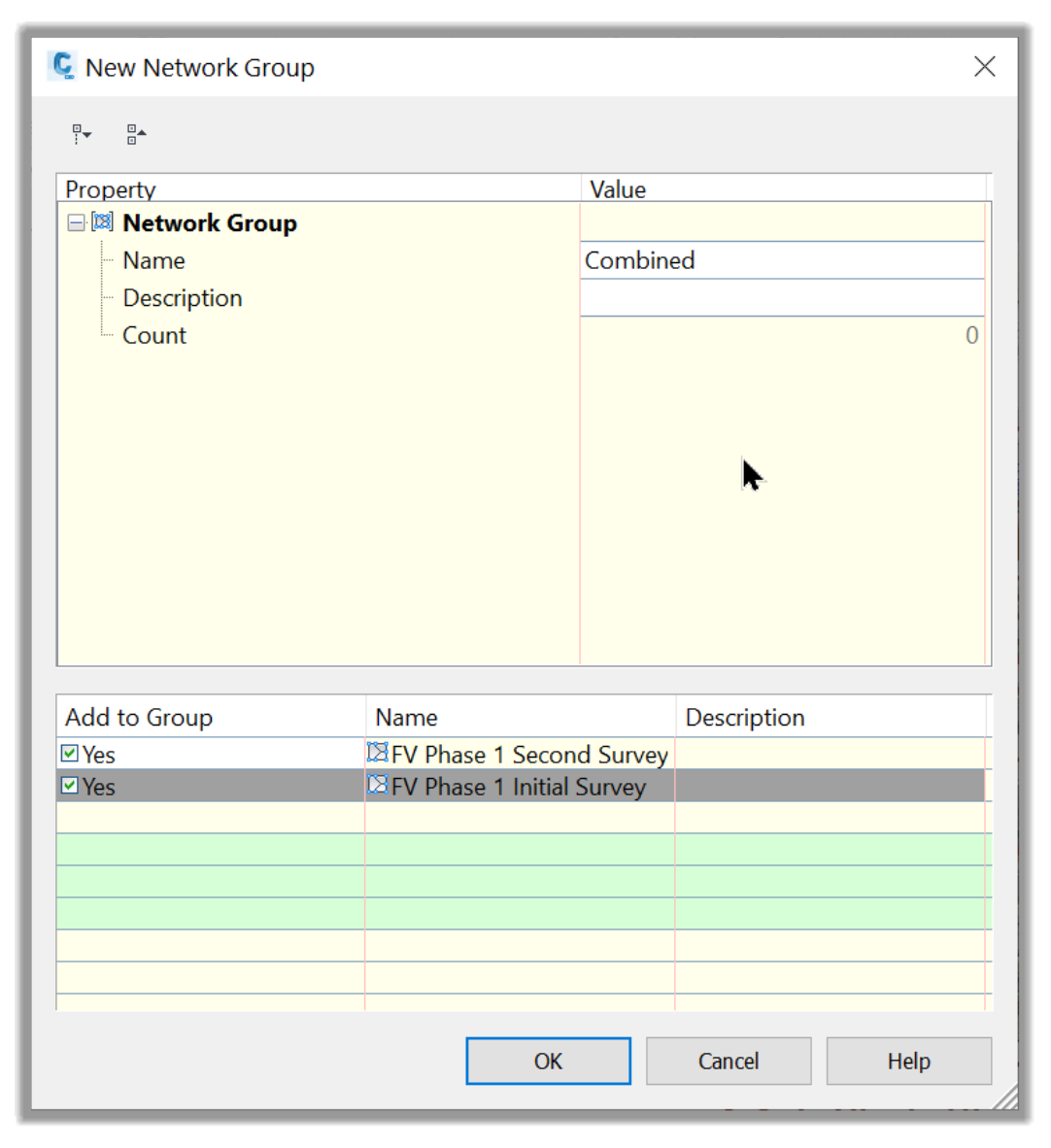
- We can also combine several networks by using Network groups. If we right-click and select New, we can combine several networks.
3.4.1.4 Survey Figures
Next, in the network section, we have Survey Figures, which are the set of linework automatically created from the field-collected data, using the linework code sets. We will talk more about the Survey Figures in the linework code sets sections.
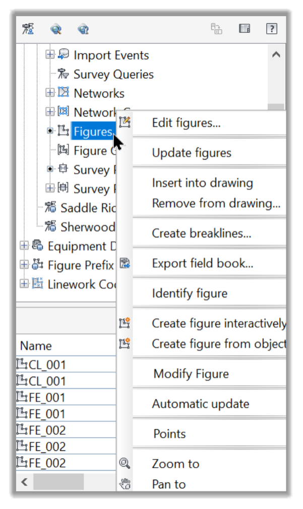
- In this section can perform several operations on the figures like editing, updating, inserting, removing, exporting, modifying, zooming, or panning.
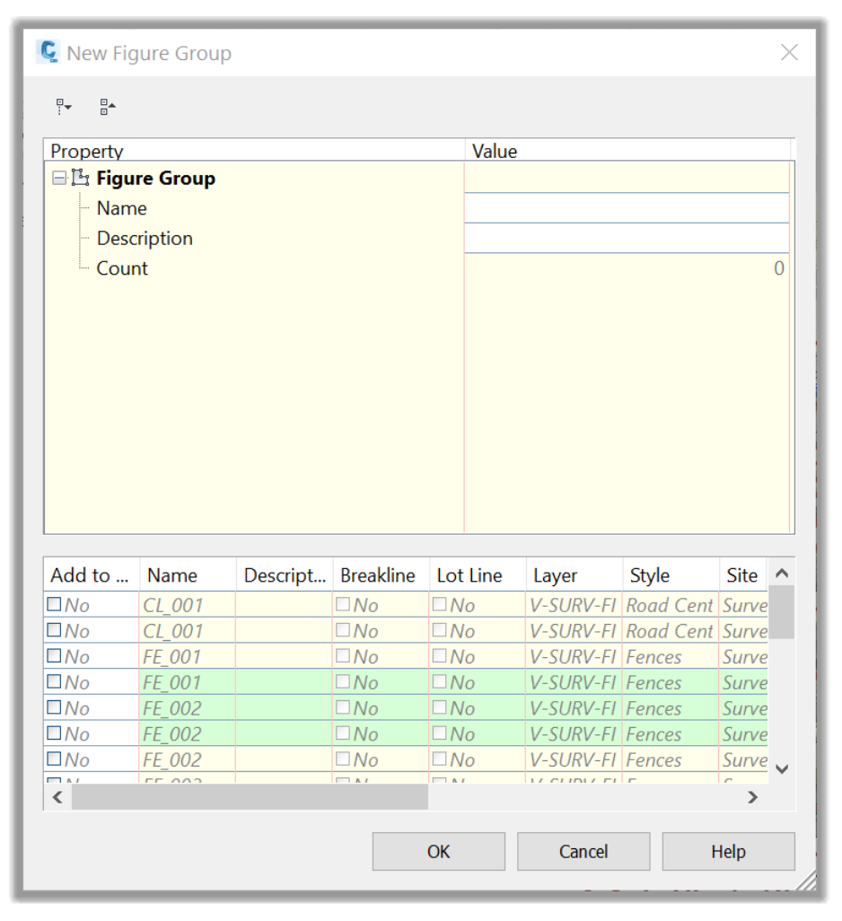
- We can also group figures by selecting them in the Group Creation window.
3.4.1.5 Survey Points
Next, we have the survey points. These are the points imported from the survey file and residing in the survey database. They are different from the cogo points, which are directly imported into the civil 3D drawing.
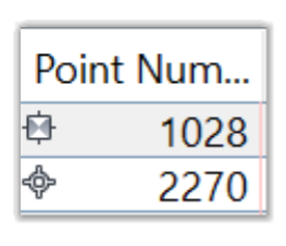
From the drawing, we can differentiate a survey point from a cogo point by looking at its symbol.
In this section,
- We can insert the Survey points into the drawing by looking at the symbol close to its number in the prospector.
- In addition, while Civil 3D points are easily edited, Survey points are edited only from the database.
- While Cogo points are shown only on the prospector tab, Survey points are displayed both the on the Prospector and the Survey tabs.
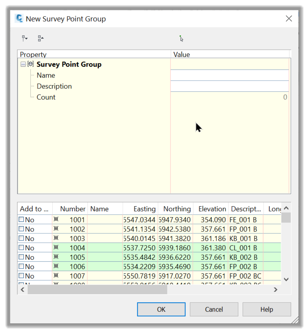
- Finally, like Networks and Figures, we can also create groups for survey points by right-clicking and selecting the list of points we would like to include in a specific group. A typical use is when we are only interested in a certain number of points. We can use the group option to insert only these points into the drawing.
Full Course and Free Book
-

Civil 3D Essentials Book and Practice Files
Course4.9 average rating (69 reviews)This mini-course offers a downloadable manual of Civil 3D. The eBook covers the features needed to successfully design most civil engineering projects, from field data collection to final design and layout.
Purchase$19.99
-

Advanced Civil 3D: Surveying and Construction
Course5.0 average rating (4 reviews)In this Online Survey and Construction Civil 3D training course, participants will learn and apply the tools offered by Civil 3D, to perform advanced survey and construction tasks.
$99 / year