Civil 3D Survey: Linework Code Sets
Field to Finish Surveying Lineworks
Product: Autodesk Civil 3D | Subject: Surveying with Civil 3D
In this exercise, we will learn about Civil 3D Survey Linework codes.
2.2.2 Lines (linework codes)
In addition to Points, in Civil 3D, we can also represent linear objects such as tree lines, polylines, utility lines, etc. These features are represented by Lines. In Civil 3D, we have different types of lines:
Basic 2D lines, Polylines, and 3D Polylines. These line types are inherited from AutoCAD, which as a reminder, Civil 3D is based on.
Civil 3D Feature Lines, which a more advanced types of 3D Polylines. They are more flexible and allow various manipulation that the traditional 3D polylines are not able to.
Then, we have Civil 3D Survey Figures. Survey Figures are to Feature lines what Survey Points are to COGO Points. The original survey lines are managed from the survey tab and reside in a database.
These different types of lines can help create an accurate and polished Existing Ground surface.
A Civil 3D Field to Finish operation allows us to automate the creation of this surface while also automatically applying our company standards, such as attributing layers, colors, line types and other specifications.
The linework created in the instrument will be converted into Survey Figures, later in Civil 3D. Let's see how to prepare to create linework (future survey figures) during a field survey, using the example of the Leica Captivate field application.
Survey Figures are created using commands called Code Sets. These commands are basically a system of codes between the Field Data collector and Civil 3D. In other words, a Code Set is the language of communication between the two tools.
A sample code can be B (to Starts a Line), C (to start a 3-Point Curve), MC (to start a Multi-Point or best-fit Curve), etc. We can create codes for almost any type of segment, including tangents, curves, circles, closed polylines, etc.
The process of creating Code Sets is very flexible and allows us to name our codes as we wish. The only requirement is to be consistent and use the same set of commands both on the Survey Controller and in Civil 3D. Otherwise, things can get quickly lost in translation.
Let's begin by looking at the concept of coding and line work,
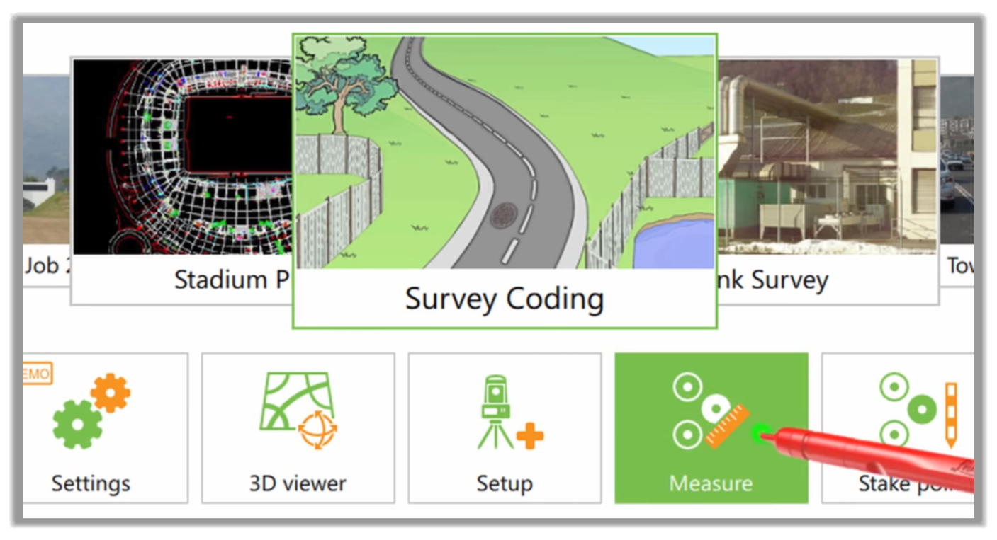
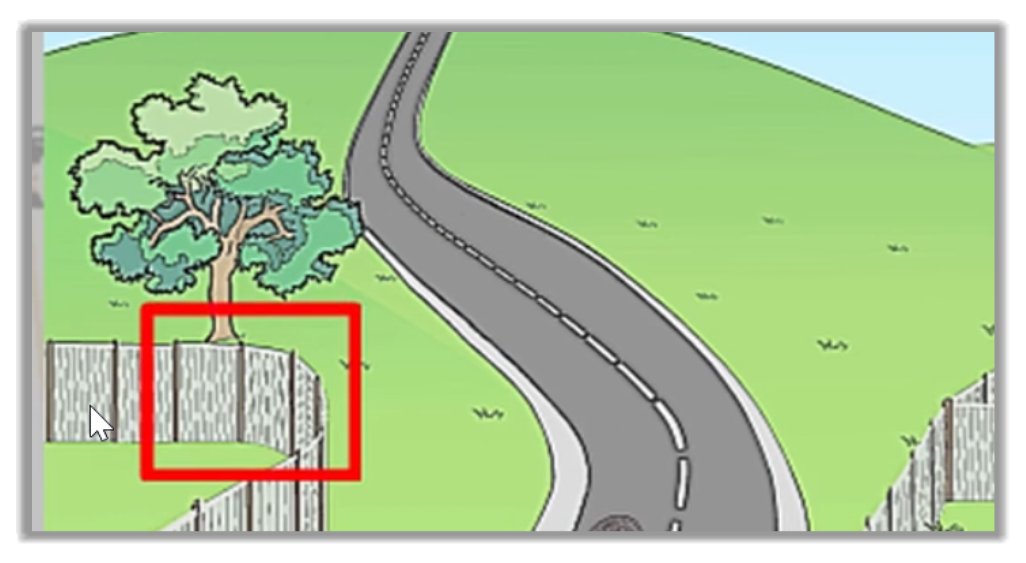
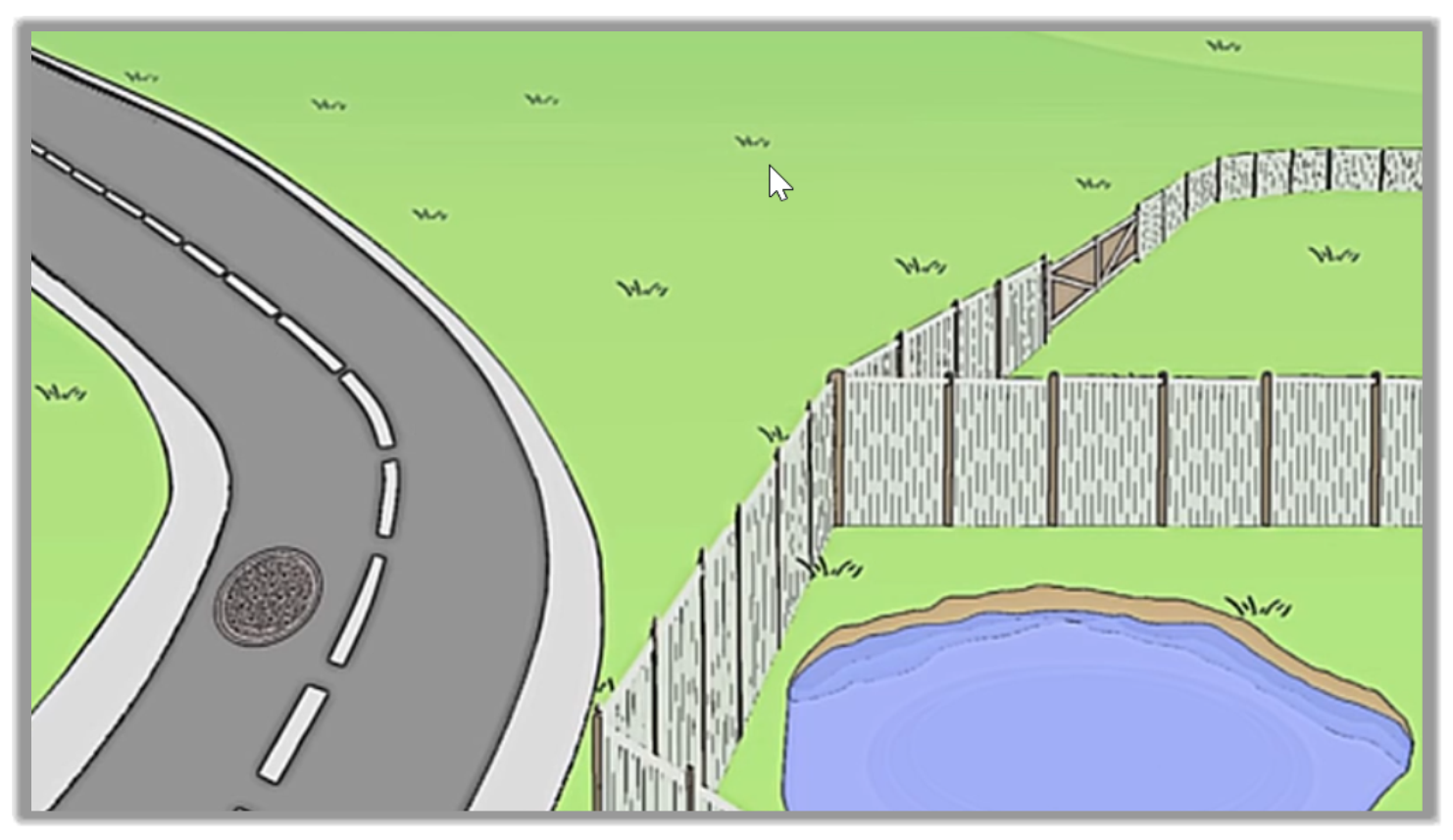
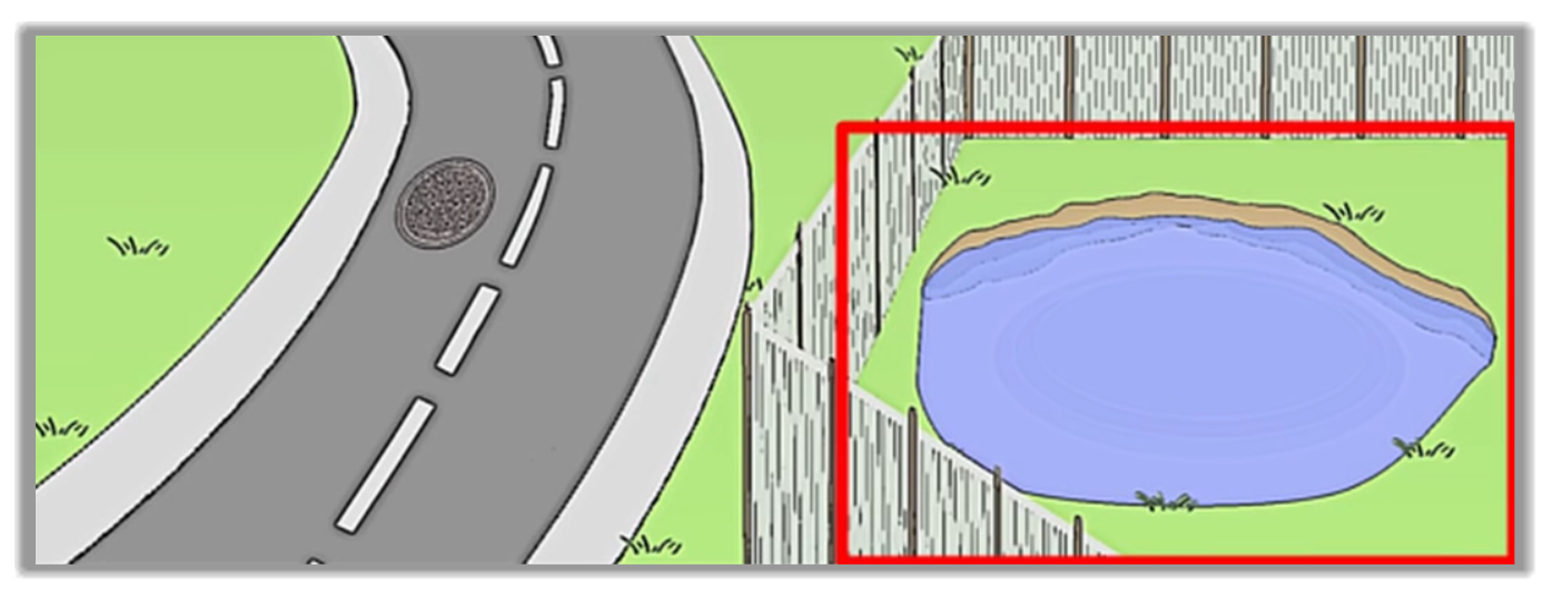
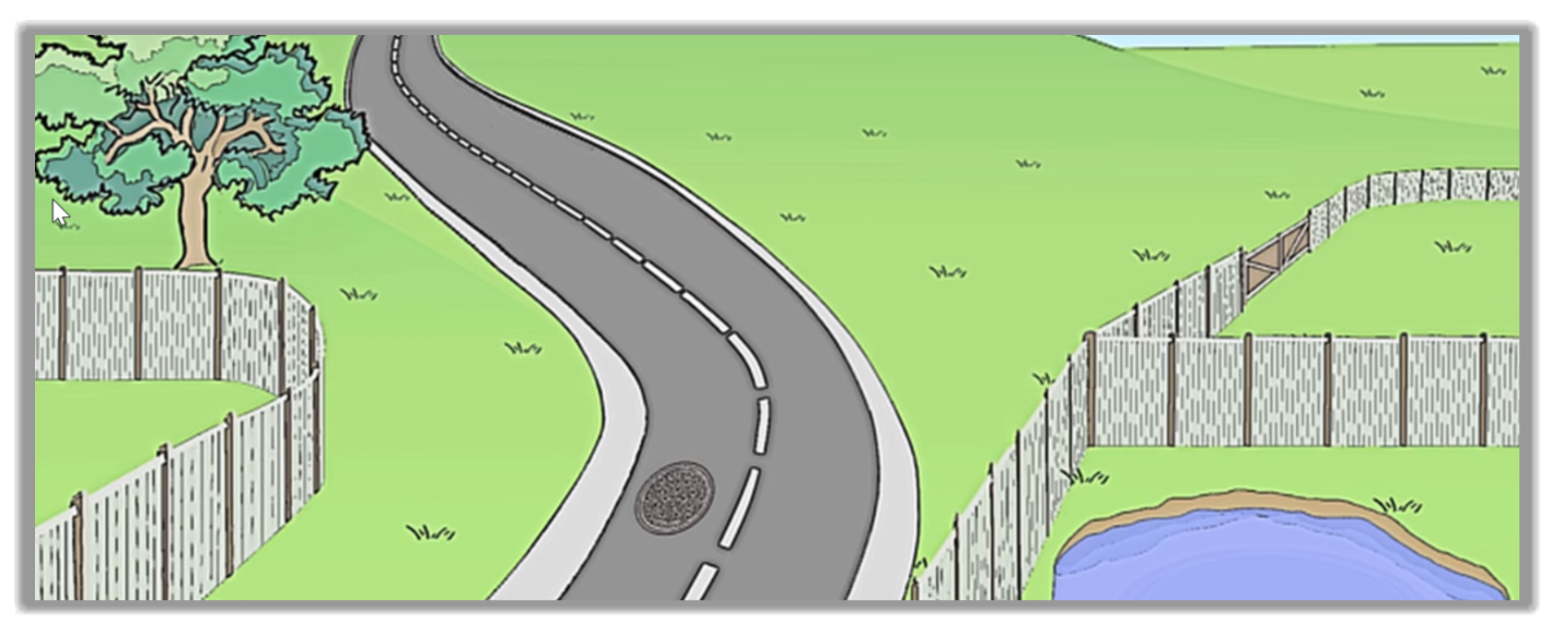
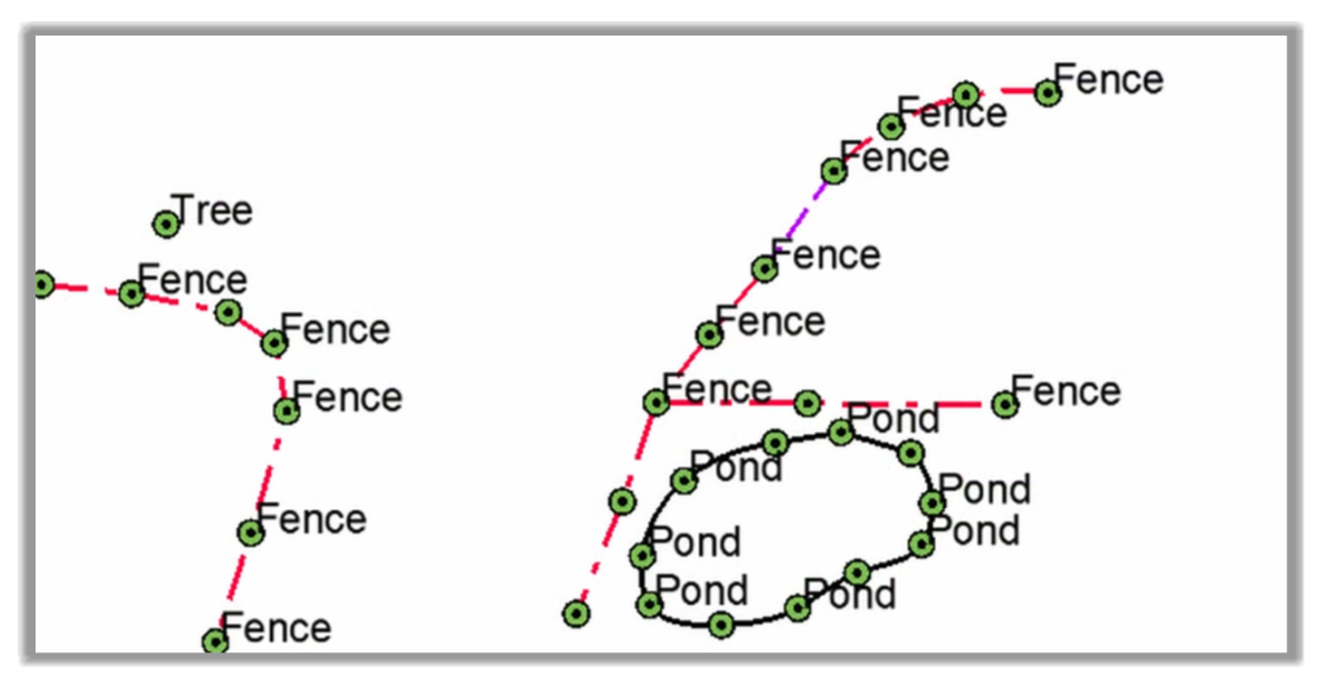
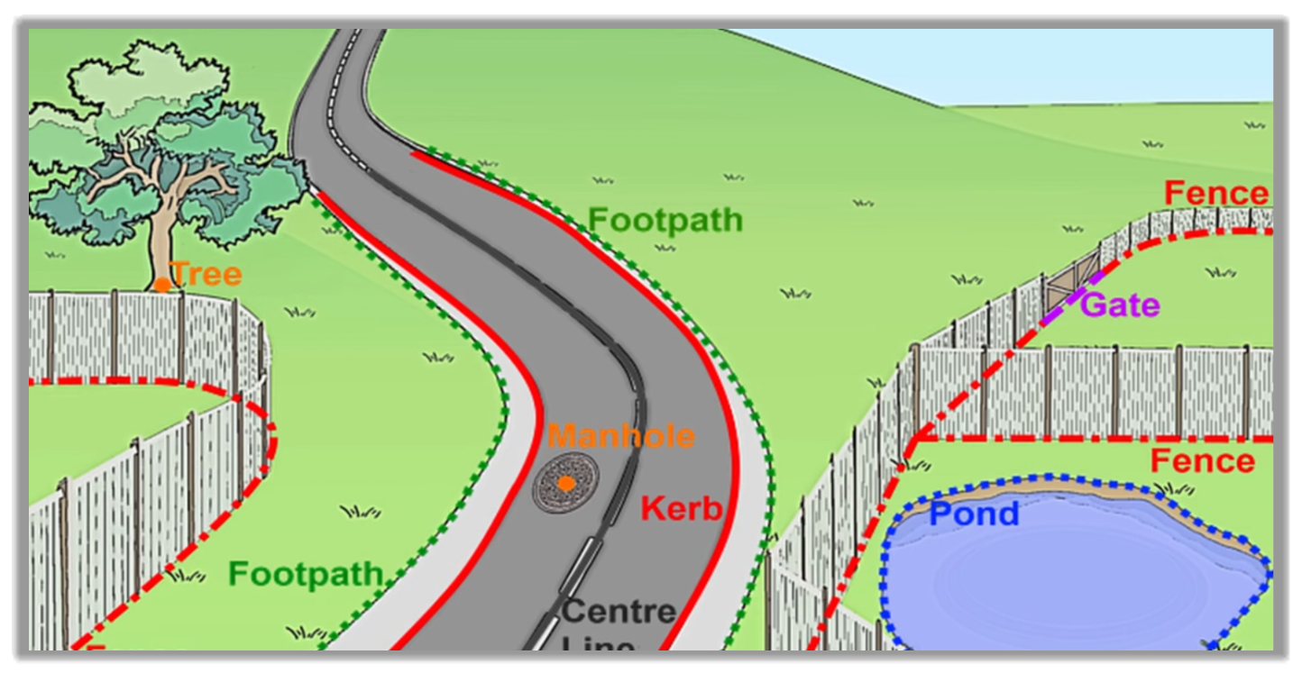
- First, let's look at the area of the site we would like to survey. We have a roadway, a tree, a couple of fence lines, a pond, and a manhole.
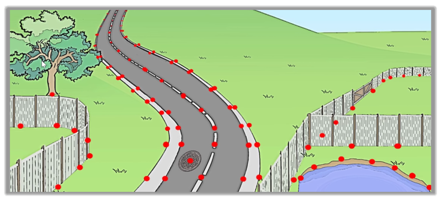
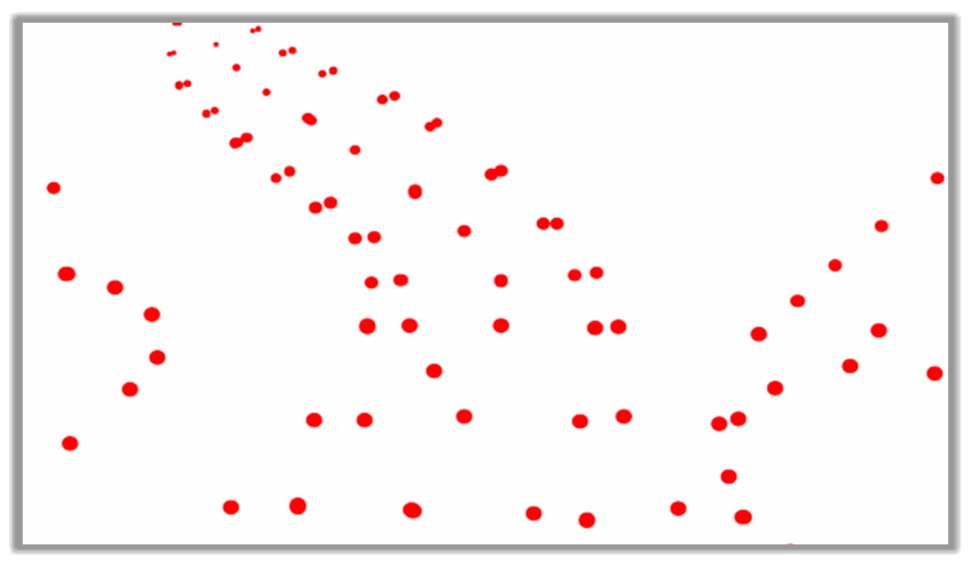
- Perhaps the easiest approach is to think about what would happen if we didn't code because we would simply end up with points. At first, this might look fine, but if we take this data into CAD, we can see it would be difficult to know what to do.
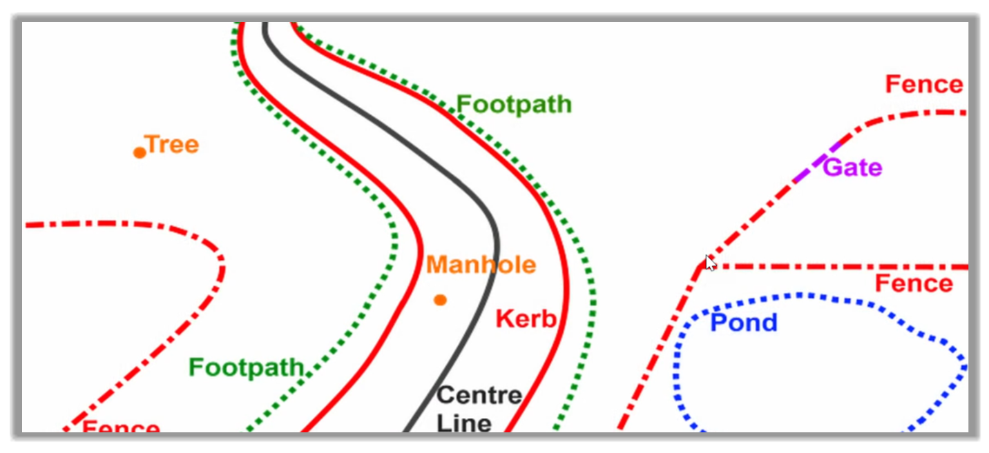
- However, if we used codes and linework, that effectively means that we are drawing the scene as we surveyed it. This means that we will end up with labeled points and lines. This makes it much easier to interpret both live in the field and back in the office.
- To summarize, the concept of coding and linework provides the ability, while on-site, to identify features to label points, create lines, and provide benefits, both in the field and back in the office. We do this in Leica Captivate using the code boxes to code and measure a simple feature. To do this, we will use an existing job with a code list attached. You should know how to create a code list in your equipment or by referring to the manufacturer's training guide. Again, this course is not intended to be a training guide on the equipment.
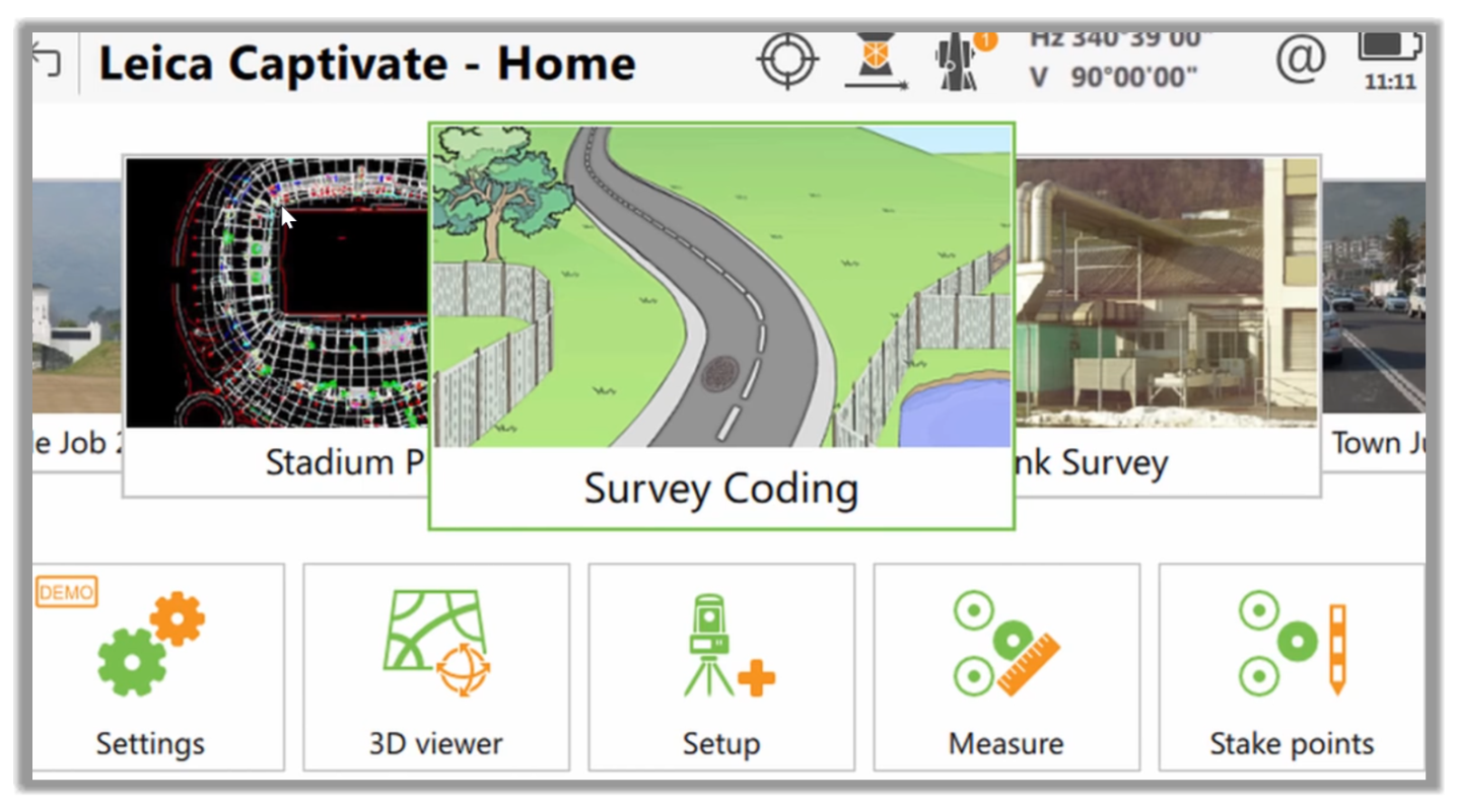
- With the current job loaded, we can tap the survey app.
- Then, in the split-screen we can go to the code boxes section.
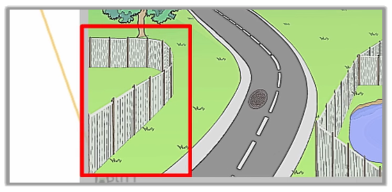
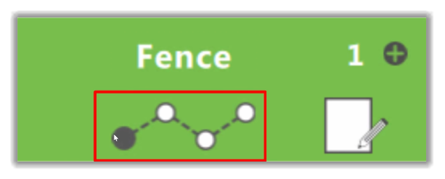
- Next, let's begin by measuring this highlighted fence.
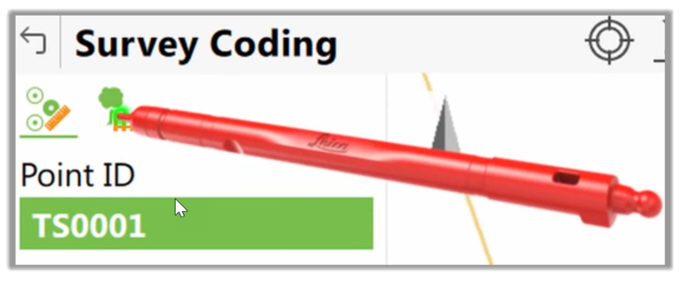
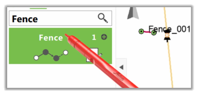
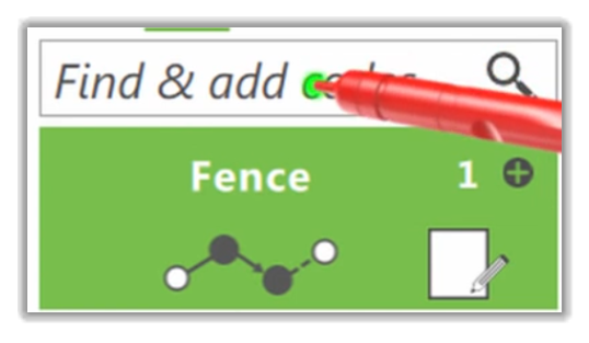
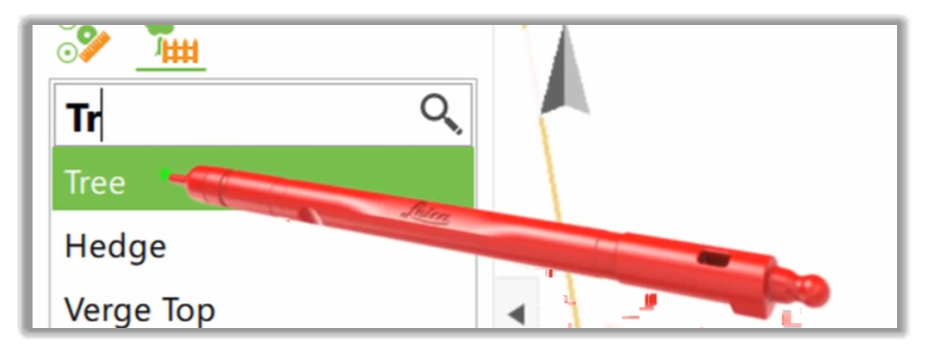
- Next, we can tap the Input Field and type the Fence code that we want to use.
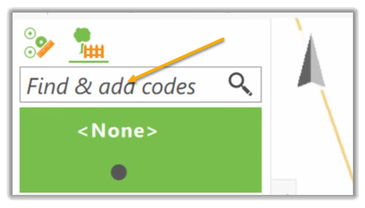
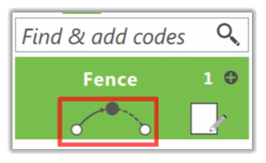
- Then, we can select it to activate as a code for the point we will measure. When we record a point, the highlighted code box will code the point for us. In this specific equipment, the code box shows us more than just the code. It also shows us the geometry information, which we will see in a moment.
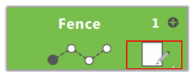
- If the code is configured to link points with a line, then here we see which line number will be used for this code.
- We also can enter attributes to store additional information with our codes.
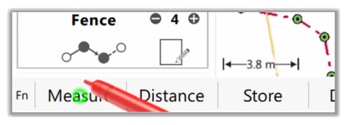
- Once we're happy with the input of our Code Box, we can measure our first point.
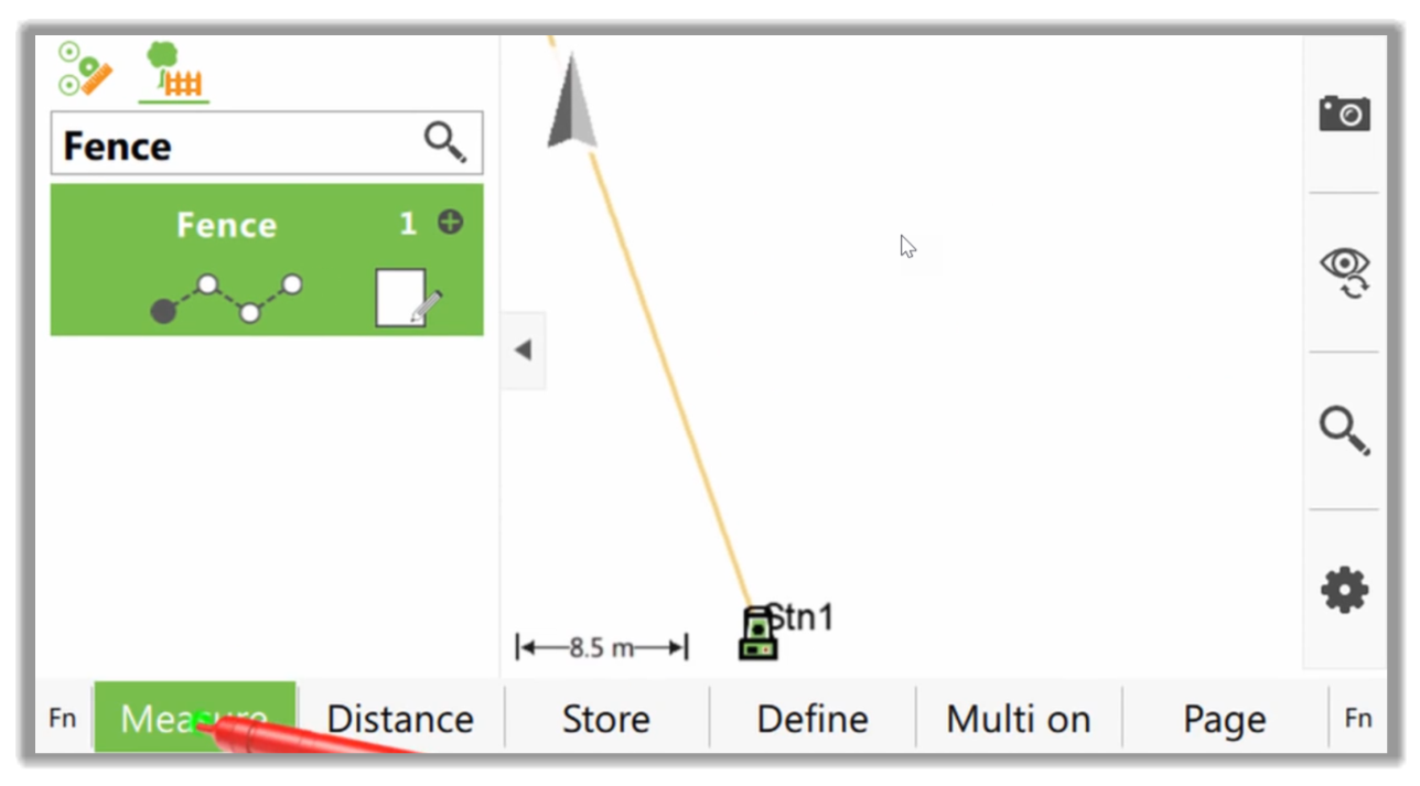
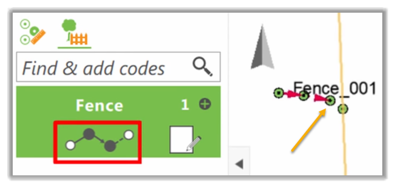
- That point is created with the code Fence. If we measure the following points with the same code and line number, they will be joined together.
2.2.2.1 Working with line geometry
Now, let's discover the geometry section of the Code Box. We have several types of geometry. In this controller, the Line geometry is used to make figures that are not straight. As we can see, we have now reached a point of the fence where it changes from straight line to a curve.
So, let's do that within the survey controller.
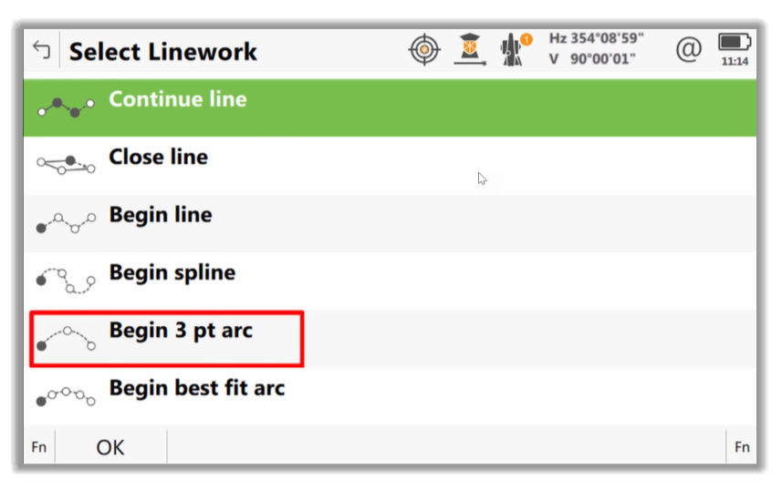
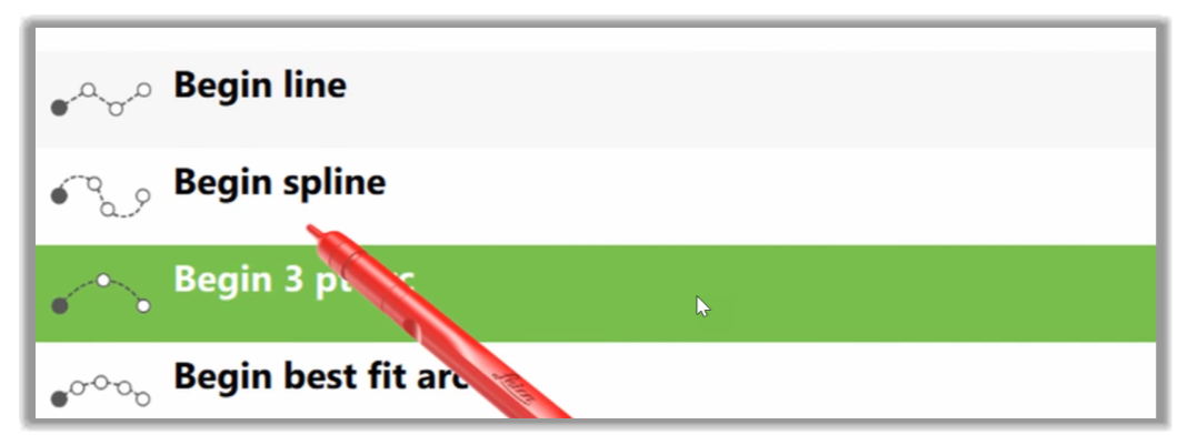
- First, let's tap on the Line Geometry section of the box.
- Then, we're able to select the type of line geometry we would like to use. In this case, we have a 3-point arc.
- Let's go ahead confirmed that. The geometry symbol in the code box now changes.
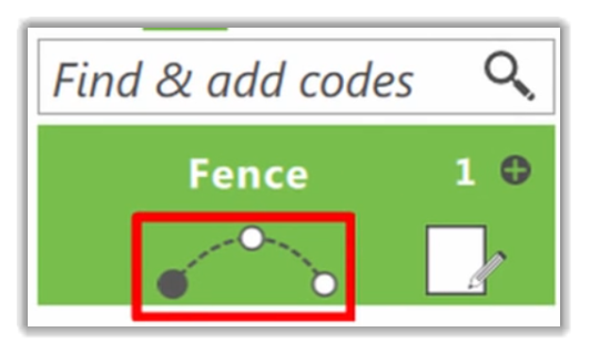
- Once we measure a point the geometry symbol changes again to prompt us to measure the second point of the arc.
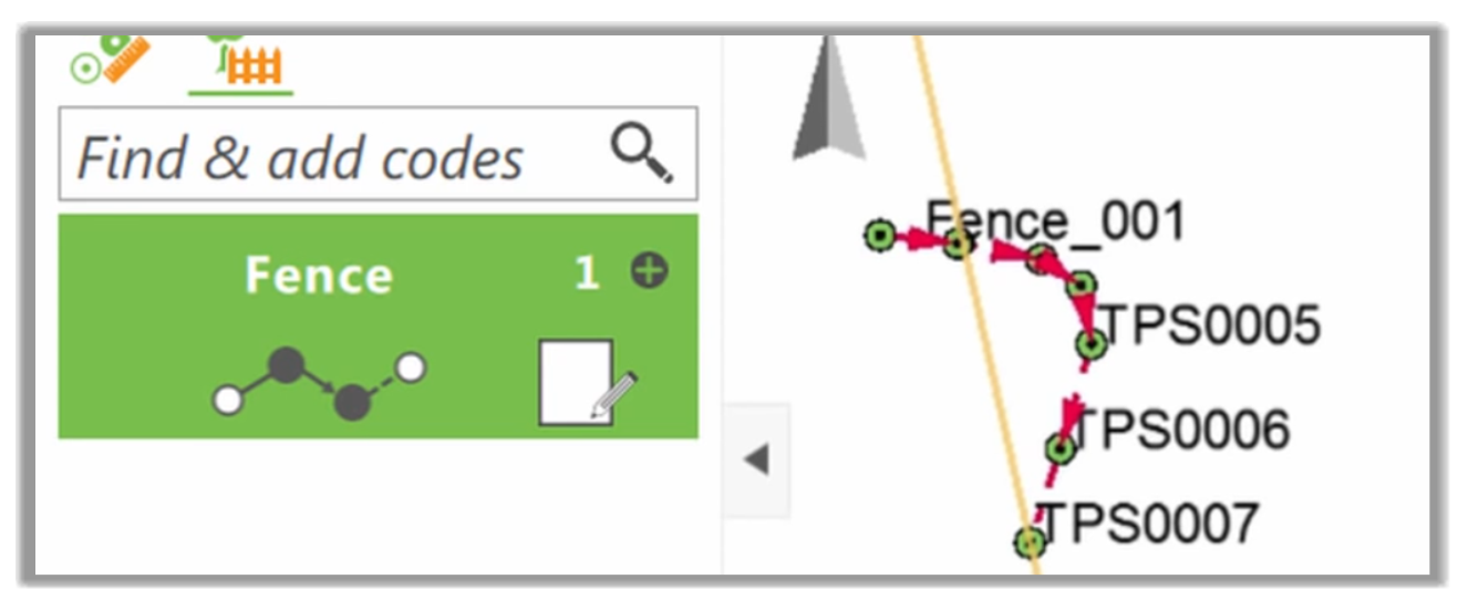
- Once we have measured again, the geometry changes to tell us that we have finished the 3 points arc, and all subsequent measurements will also be part of a straight section.
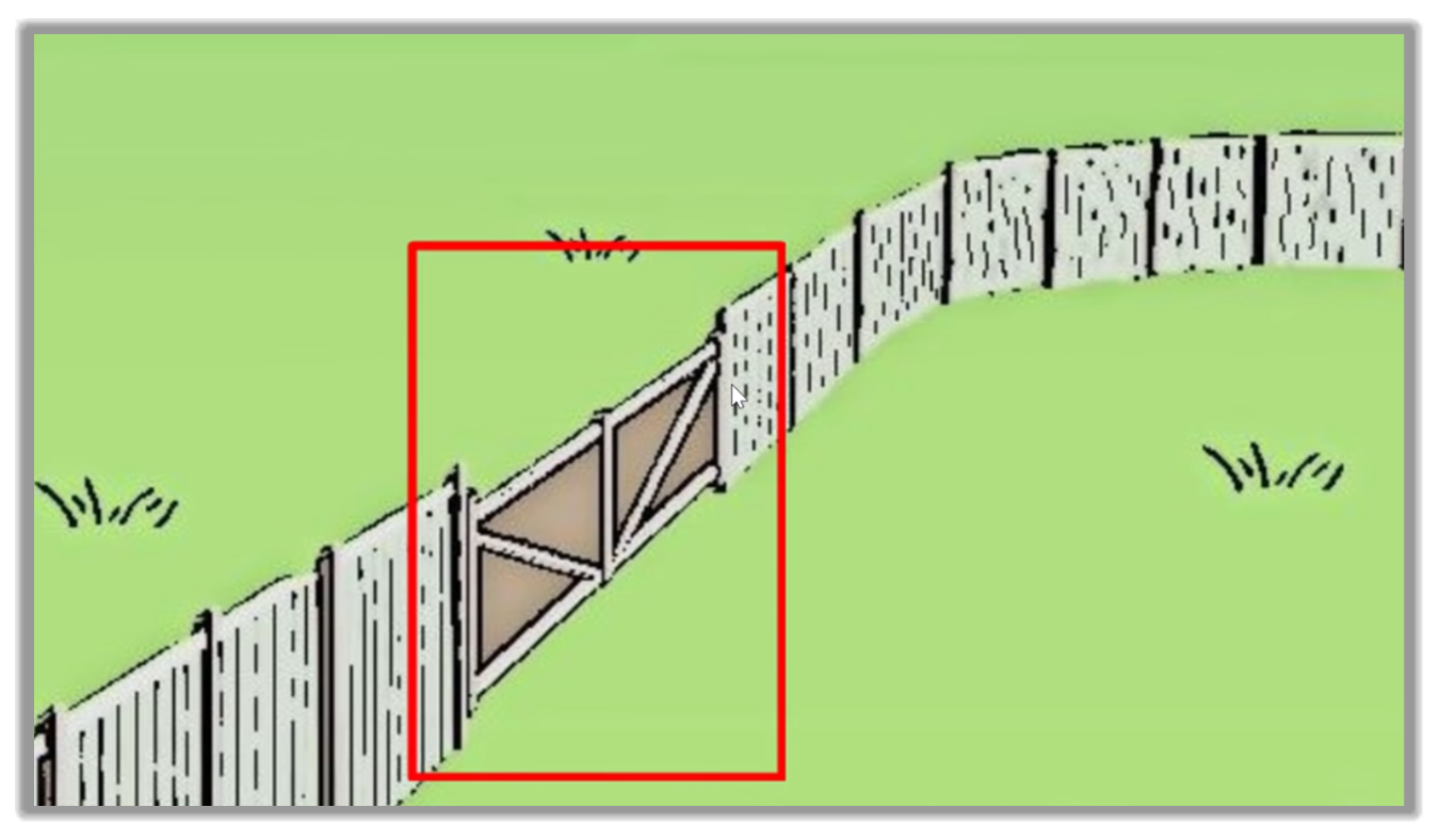
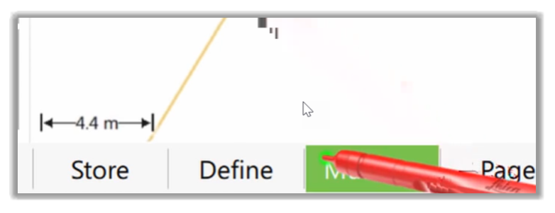
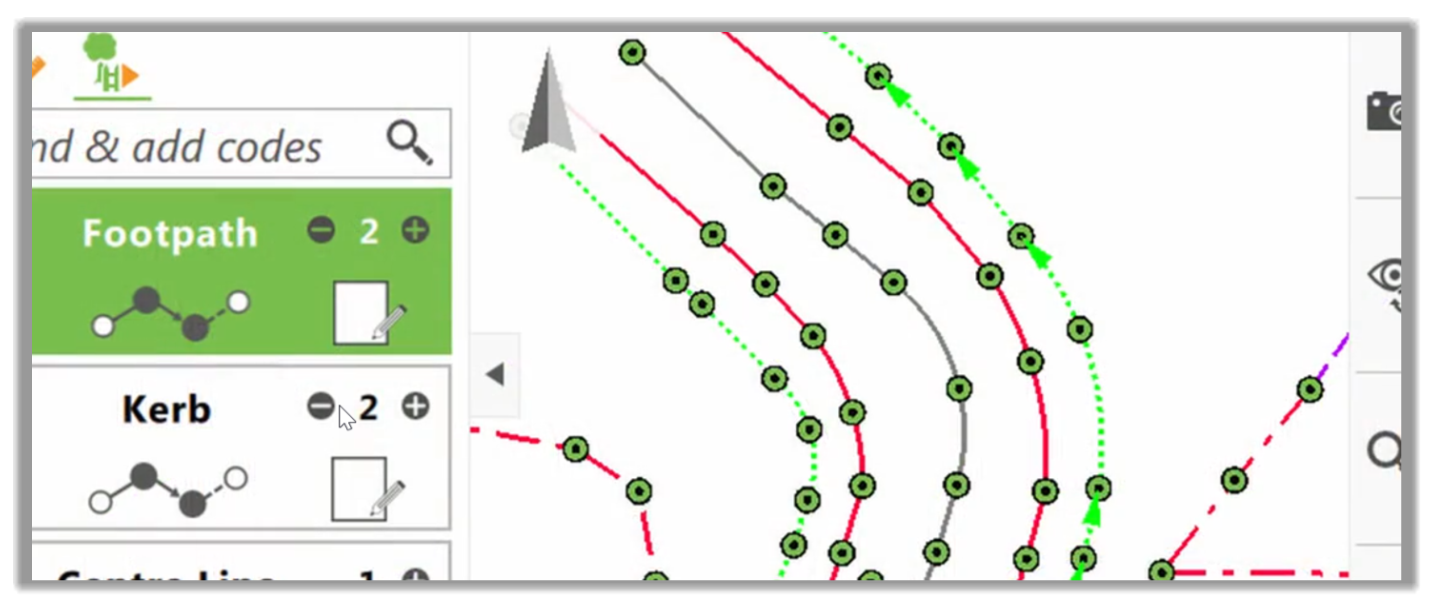
- As we continue to make more measurements onto this fence, we can see that we have quickly and easily created a line that goes from straight to an arc and then back to straight once again.
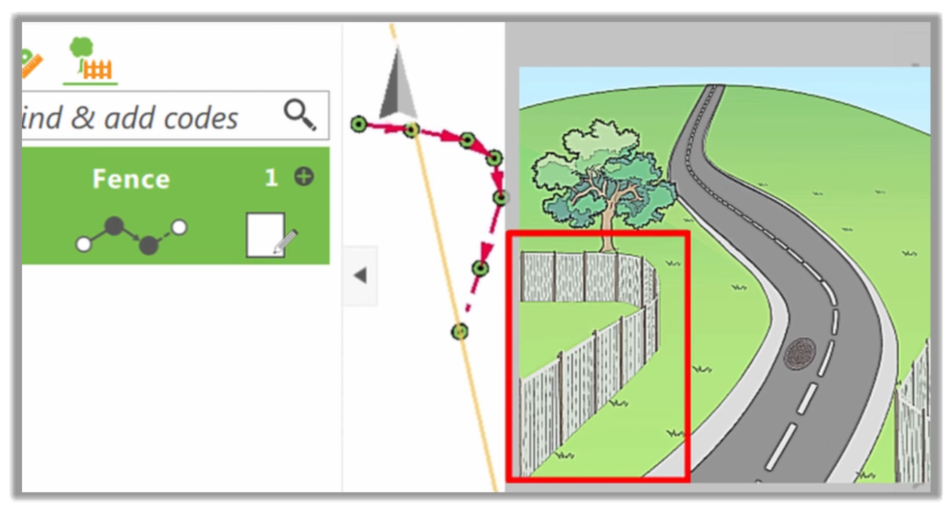
- If we zoom in and take a closer look at the fence, we can see that it accurately represents the situation that we have on-site.
2.2.2.2 Creating Multiple Codes
Now, let's see how to create other types of code lines. Let's turn our attention to the area just across the road, where we have a fence going into a gate, then back to a fence again. Then we have a T junction where two fences meet.
To measure this, we need to create a new fence. Let's see how to do that.
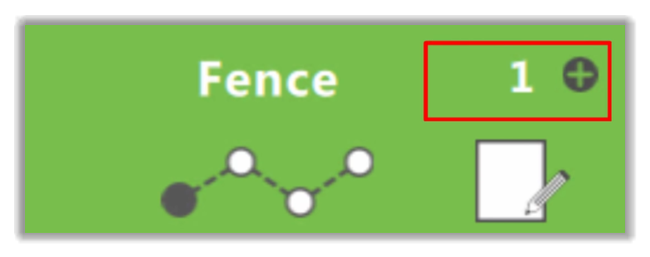
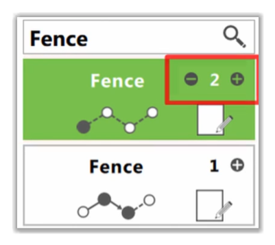
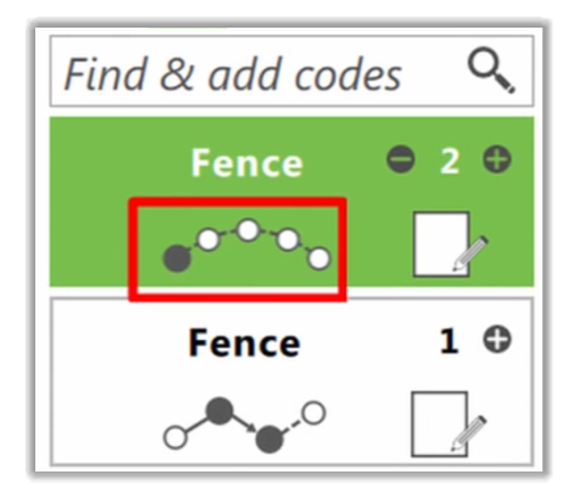
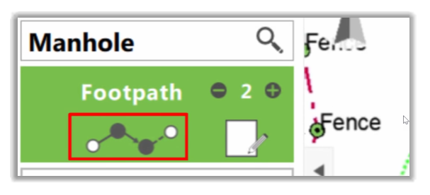
- We could use the existing line number and increase it to two.

- Or we could, as we will do here, select a new fence box.
- This shows that we can have multiple code boxes using the same code. What is important is which code box is highlighted and what line number is active in that code box. Civil 3D will only read the code and work with the numbers, as they will be part of the description. We can see when we added the new code box the App automatically found and selected the next line number for us. Civil 3D will recognize these as two separate objects, Fence 1 and Fence 2.
- This fence starts already on a curve, so we need to tell this to the controller. To do that, let's click into the geometry, but this time, instead of using the 3-point arc, we're going to use the best fit curve to model our curve over multiple points.
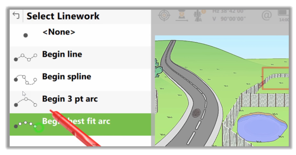
- So, let's select Begin best-fit arc and press OK.
- Now we can see that the arc geometry in the code box with multiple point curve.
- Now, as we measure a point, we can see that the arc geometry is telling us that we're continuing our multiple points or best-fit curve.
- After a few measurements, we realize that we are now getting to the point where the fence on the gate is connected.
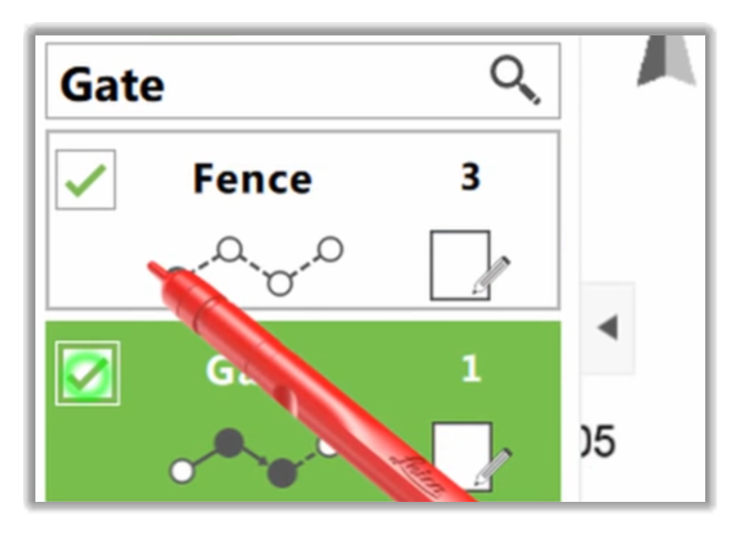
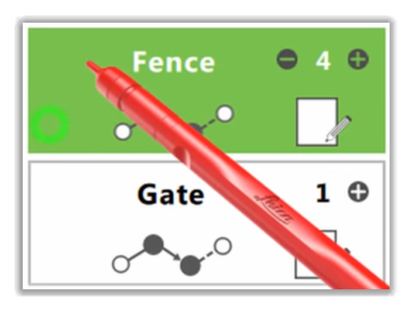
- After that, we actually have a connection between the gate and a new fence. So, let's see how to handle this. The first thing we need to do is to prepare a Gate code box.
- Once we have that, we can use the new function, Multi, to select multiple codes to be used simultaneously.
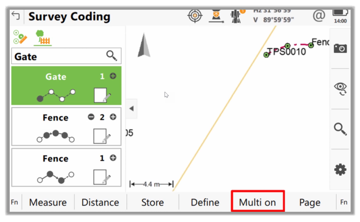
- In Captivate, the Multi On allows us to select multiple codes at the same time. This option will enable us to use checkboxes to select which codes we would like to be stored. Here, we see our new gate on the existing fence.
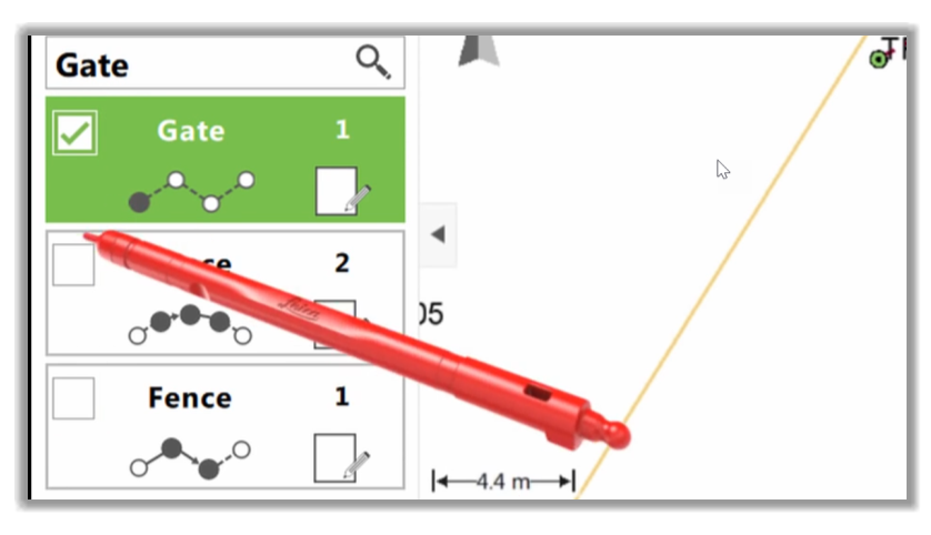
- It’s worth noting what the software will do when we press measure. It will make one measurement but store it twice, creating two points with different codes, as these two points are in identical positions, and any lines going through them will indeed intersect in 3D. This will not be a problem for Civil 3D. The points will just be treated as crossing breaklines.
- Now, when we press to measure, we know that both codes will be used simultaneously. We can notice that once the measurement is stored, Multi On is switched back off because, in most cases, multiple coding is only required one shot at a time, at intersection points. However, in this situation we straightaway need to turn multiple coding back on, as we now measure where the other side of the gate meets our straight part of the fence.
- So first, we’ll use a Plus button to create fence line number three.
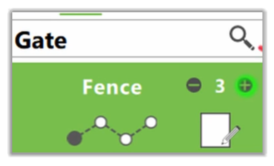
- Then, we will turn Multi coding back on.
- Next, we will activate the gate code box as well as Fence 3.
- After that, let's press the measure to store our second point on our gate and begin our third fence line.
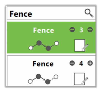
- It is worth noting that whichever code box was highlighted when we press Measure jumps to the top of our code box list. In this case, that was the gate, but we want to use fence line number three to continue creating the rest of the fence. So, let's tap on that box before we press measure to continue our fence line.
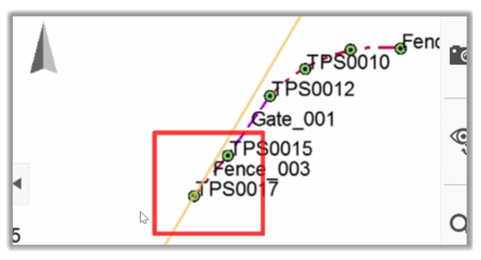
- The next point we want to measure is another point that requires multiple codes, although, in this instance, it's actually the same code twice because it is our fence T-junction. It's not like a Fence meeting a Gate. All sections are fences. However, this doesn't matter to some survey controllers. The process would be the same as with different types of codes.
- With the current controller, we need to add a new code box. So, let's turn on multiple coding.
- Then, we will select the codes that we want to store, which will be Fence 3 and a New Fence 4.
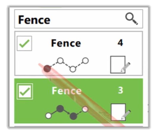
- Next, we can press Measure.
- After that, we can choose which of the fence lines we would like to continue. In this case, we’ll continue Fence 3. So, it needs to be the code box that is highlighted.
- Then, after we finished that line, we can simply tap on the code box of Fence 4 and measure the remaining points on that one, too.
- We can now measure the final points onto that fence line.
2.2.2.3 Creating New Codes and Closed Lines
We can now look at two more features and options: creating new codes and closed features such as building footprints or ponds, for example.
- Let's use this pond as an example for both cases. As we start typing the code Pond, we notice that it's not in the drop-down list. That is because it does not exist.
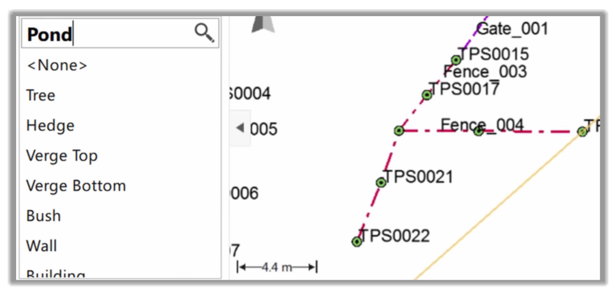
- However, that's not a problem with this controller. We could just press Enter to add it to the code list. It should be pretty standard in other controllers to create a new code on the fly.
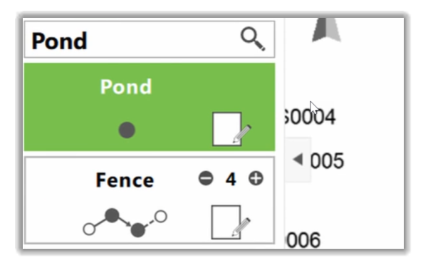
- However, because this is a new code, it is initially added simply as a point, as we can see from the geometry.
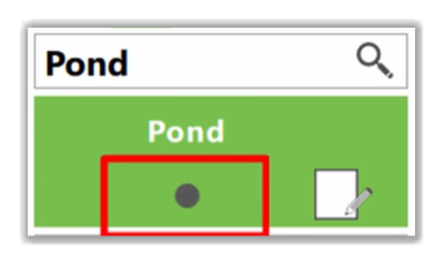
- So, if we tap on the geometry, we can change it. Because the pond is an irregular shape, we'll use spline functionality.
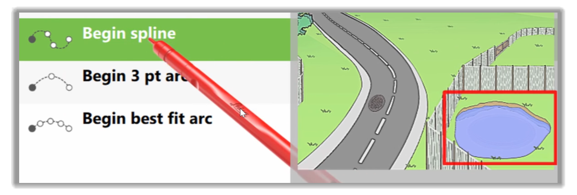
- With the Spline figure selected, we can begin to measure our pond. As we are measuring points, the Code box highlights the points being created, as we have seen in this video.
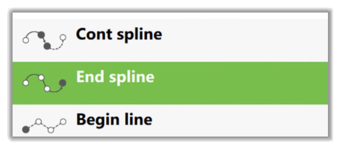
- Let's just measure the first couple of points and then skip ahead to a location where the pond is more regular, and we want to switch back to using straight segments again. This is quickly done by entering into the geometry and selecting End Spline.
- Now, any point we measure will be added to a straight segment.
- As we have now come ultimately around the pond back towards where we have started, it makes sense to close the line. So once again, we enter geometry, but this time, we choose the Close line function.
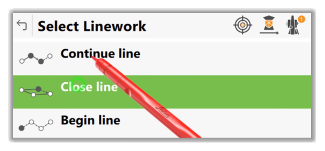
- Now, when we press to measure, this last point will be added. But the line will extend beyond this point and close back onto the very first point.
2.2.2.4 Coding and measuring a single point
One of the most significant benefits of coding line work is that we can review how the linework looks right in the field before exporting to the office. Imagine the convenience of correcting the mistakes while still on-site instead of making another field trip.
Most controllers offer this type of functionality. The controller we are using for this demo is called the 3D Viewer. In this picture, we can see the site we're attempting to survey.
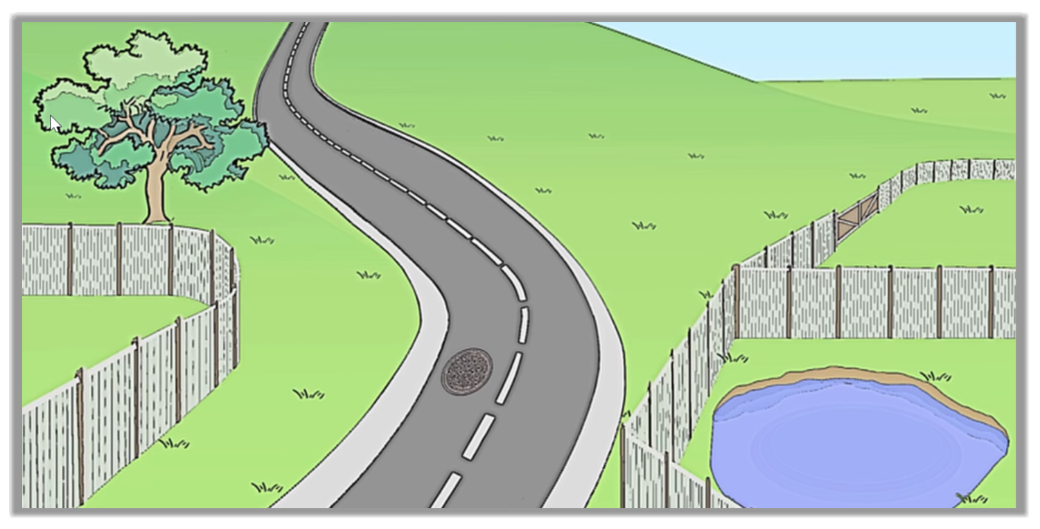
We haven't surveyed the road, but everything else should have been measured.
Let's switch to the 3D viewer. As we pan around in 3D viewer, we realize we've miss something, a tree.
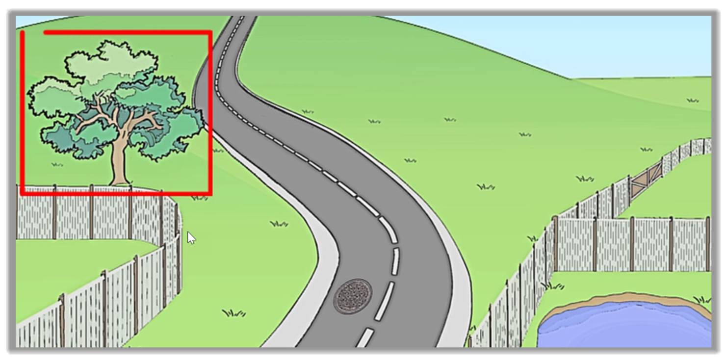
It's a large tree, and it indeed should be surveyed, which brings us on to the final feature to study, Coding, and measuring a single point.
- To measure a single point, as we have done before, let's tap into the input field and start typing the code we wish to use.
- Then, when we select it, the code boxes are created for us. We can see that it is created as a point. This will not start a line, and this time, that is correct.
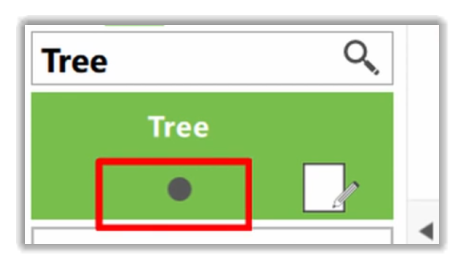
- So, we leave it as it is and just press Measure.
- And with that, we have now finished the fences, pond, and the tree. Next, we survey the road to discover a feature called Auto survey.
2.2.2.5 Auto Code Selection
With Auto code selection, the controller will automatically suggest the next code to measure, allowing us to measure repeatable features quickly and easily.
- As we can see, we measured most of a site, but the road was left completely un-surveyed. So, let's survey the road now.
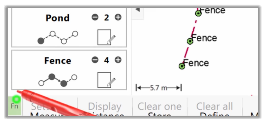
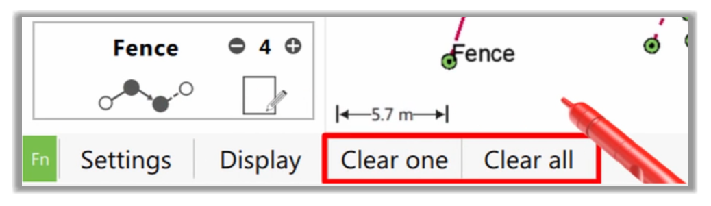
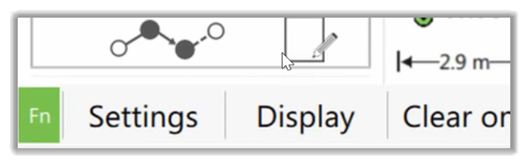
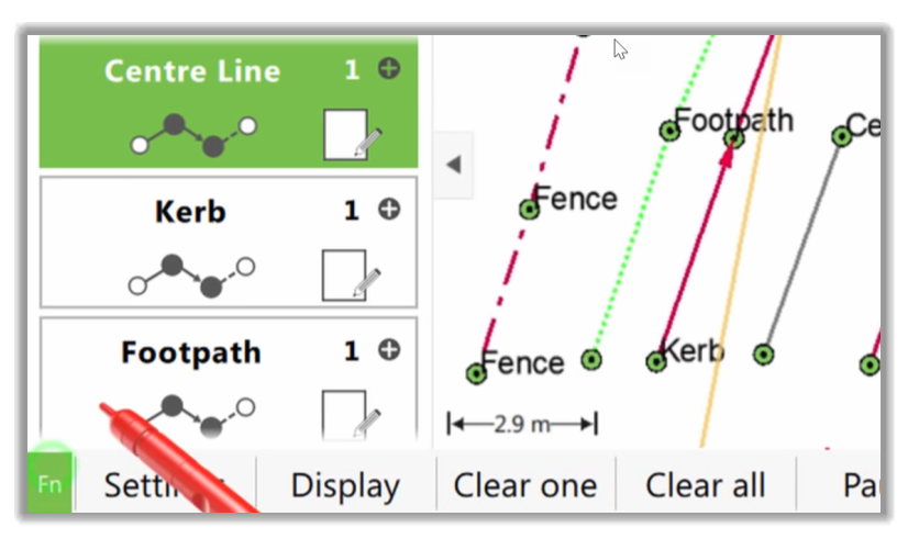
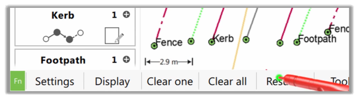
- First, we will clear the list of code boxes and build a new one on the fly as we measure the road. We clear the boxes by going to the second level of Function keys and selecting one of the Clear options.
- Here, we'll clear all boxes, not just one.
- Now that the code box list is empty, we can build a new list, selecting each code as we need it when going across the road.
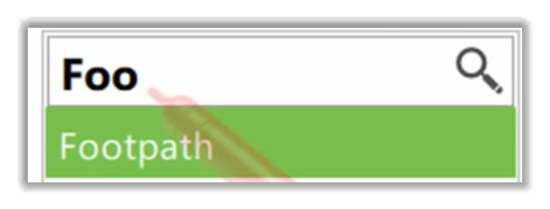
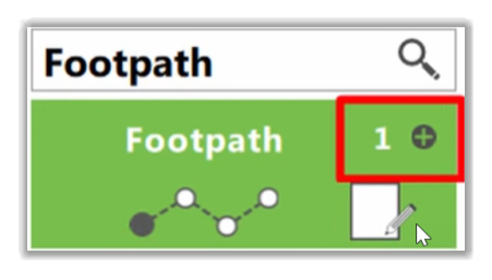
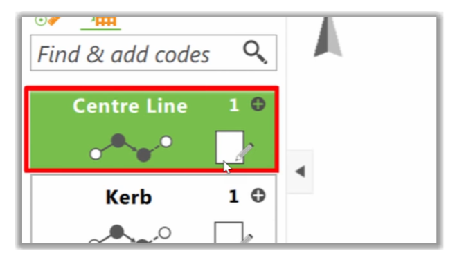
- Let's start at the very left edge of the road with the code footpath or sidewalk.
- We know that this will be the first sidewalk that we measure on the site to leave this as line Number 1 and measure our first point.
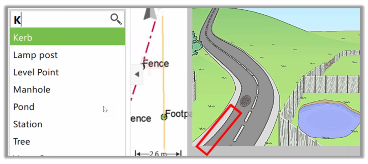
- Instead of continuing our sidewalk string, we can move across to the second feature in this cross-section. Here that is a Curb. So, we can select that code on the list.
- Again, it would be line Number 1 because it is our first Curb.
- Next, we can Measure the starting point of the curb.
- As with the sidewalk, we're not going to measure a second point on this curb line. Instead, we will go across the road to the Centerline of the road.
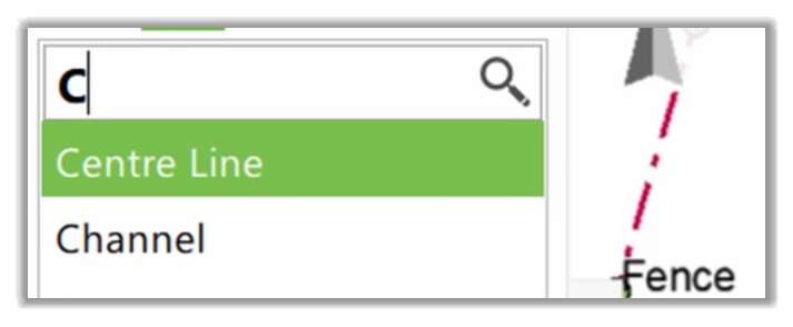
- Once again, we will select the code also, leaving it to line Number 1, then we will measure its starting point as before we will only measure one point on this line before we continue across to the other side of the road.
- The next line we need to measure is again a curb, our second one for this site.
- As we already have one curb and now adding another, the survey controller recognizes it and has automatically set the line to Number 2.
- So again, we just need to press Measure to record our first point of the line. Then we can move across the road to the final part of our cross-section, our second sidewalk line. As usual, we just need to measure its first point.
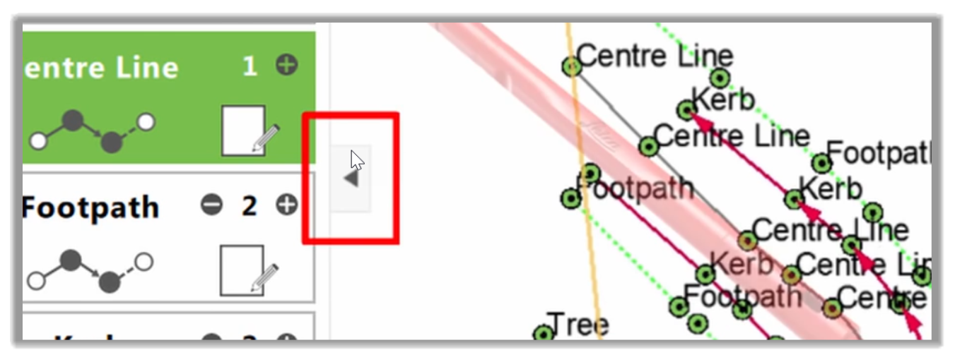
- Now that we have walked across the road measuring every line's start, we have built up a list of code boxes that perfectly matches the cross-section of our road. This will allow us to use the Auto code selection feature.
The Auto Code feature is where the controller automatically suggests and selects the next code for us.
- We activate Auto Code by going into the second level of the Function keys.
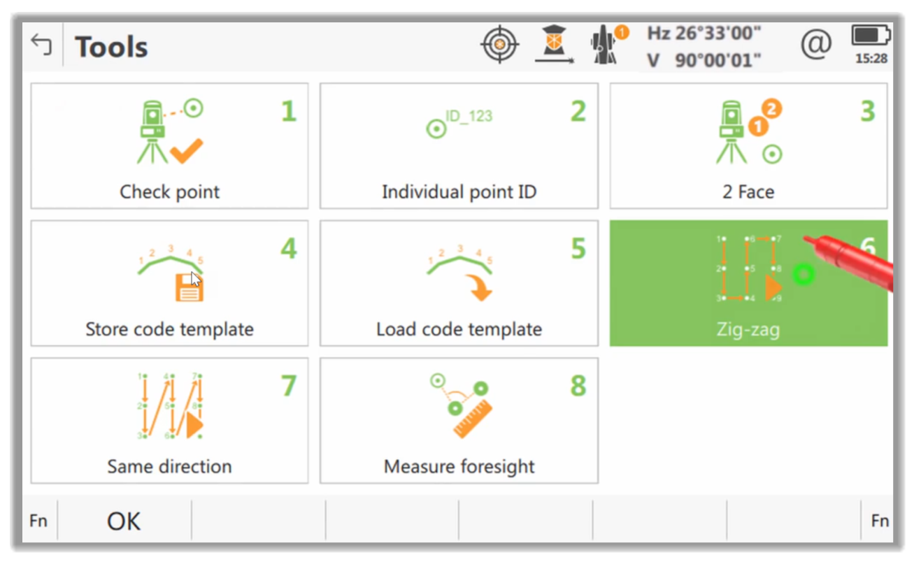
- Then, we need to enter into the Toolbox.
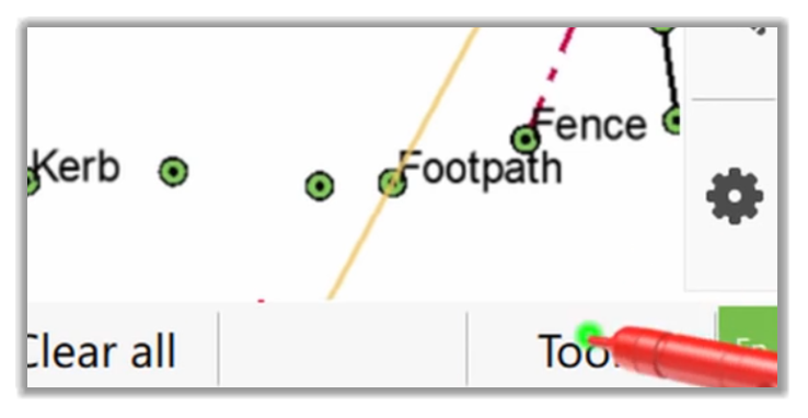
- In the Toolbox, there are four options to do with auto code selection. The first two are the Storing and Loading of code templates.
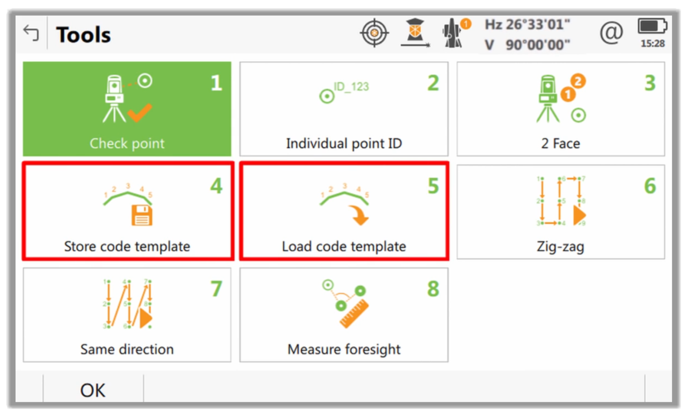
- If a list of code boxes we have created is one that we want to save and use repeatedly, we can do that here in the Store code template section. Or if we have a previously saved list of code boxes, we can load them using the Load code template section.
- The next two options allow us to start auto code selection either by zigzagging or always in the same direction.
- Zigzagging is where it is assumed that we want to use each of our selected codes first in one direction and then turn around and use them in the opposite direction. Then, back again in the original direction, and so on.
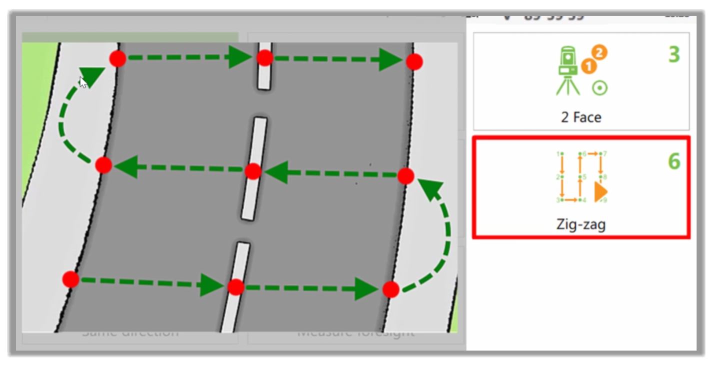
- We would do this by reversing the order we used to code for each pass through.
- The Same direction option assumes that we always want to use the codes in the same direction as they exist in the template.
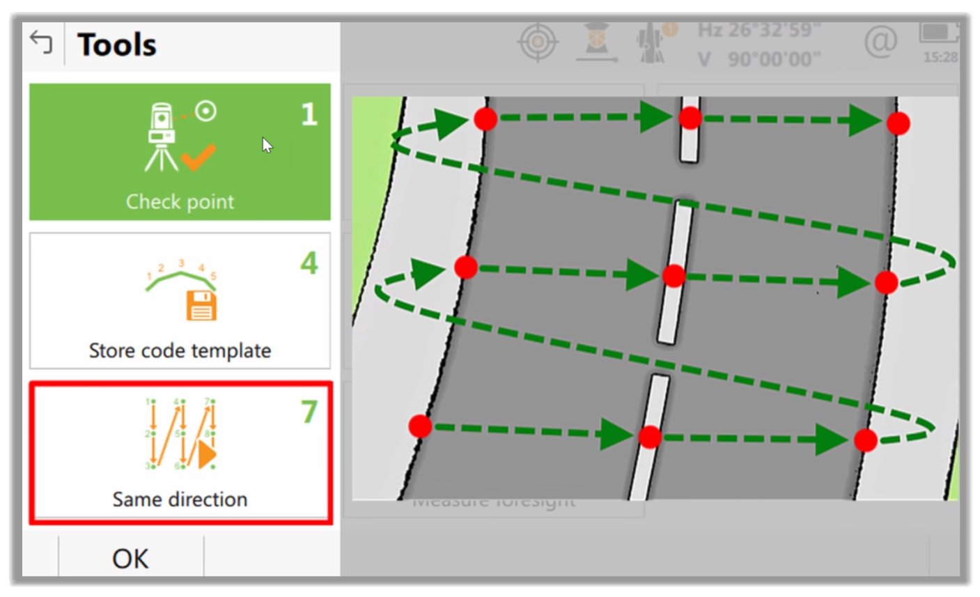
- So as soon as the last code is used, the survey controller would loop back around and select the first one again for us.
- If we had already turned on this functionality, then we would also have the option to turn it off on this screen. But for now, as it is not yet on because we don't need to store or load a template, and because our example best suits the Zigzag mode, we’ll simply select zigzag.
- Now, our job is just to measure the point that the Survey Controller is prompting us for. As the sidewalk (footpath) is the highlighted code, we need to measure the second point on our sidewalk.
- Once we have done that, the Controller automatically moves to the Curb code. So, we need to measure the second point on that curb.
- Now, we’re prompted to measure a centerline. So next, we'll do exactly that and measure the second point on that line.
- Because the survey controller helps us, we are moving to the next point on the suggested line and press Measure.
- This is making our job easier as a code selection is automatically made to focus on measuring the right point on what is around us. This increases our efficiency and increases our safety, which is especially important on active construction sites or when working close to busy roads.
- Now that we're reaching the end of our road cross-section, we can see the Zigzag function in practice.
- After we measure the last code, Leica Captivate keeps the focus on that code so that we can use it to measure the starting point of the next cross-section.
- All of this Auto code selection is great but sometimes, there are additional features, this utility hole, for example, that are not in our list of code boxes.
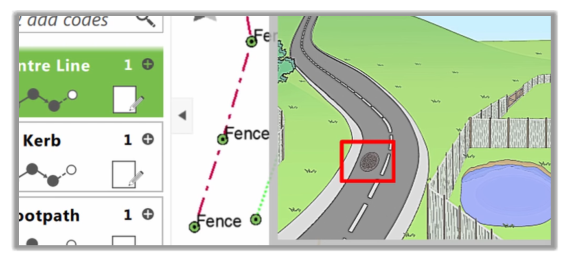
- To solve this, we would need to Pause and later Resume the Auto Code function. Let's see how to do that.
- As we noticed earlier, we may come across survey features not coded in our Auto Code function. We can skip them and come back later to record them, but that's a risky proposition as we may forget, especially if we are dealing with a long road. That's where the Pause and Resume function comes in.
- To activate this function, we need to go to the second level of our Function keys.
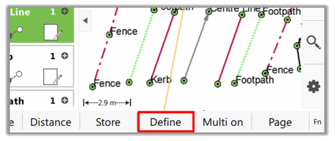
- Once activated, this time, we need to press Pause, which stops the auto code selection. This means that it prevents the application from moving the focus to the next code box and allows us to start editing those code boxes.
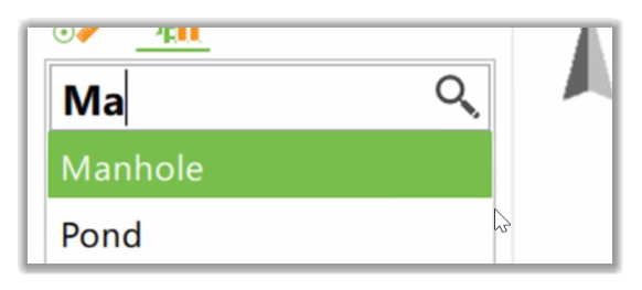
- We could now use the Define button to change one of our code boxes to Manhole.
- Instead, let's add a new code box and use it to measure the manhole.
- Here we can notice that there was no automatic focus or code box movement after measuring the point. This is because we paused the auto code selection.
- As there is only one manhole to measure and we do not need to leave this code box in our list, we can right away remove it by selecting to Clear one code box.
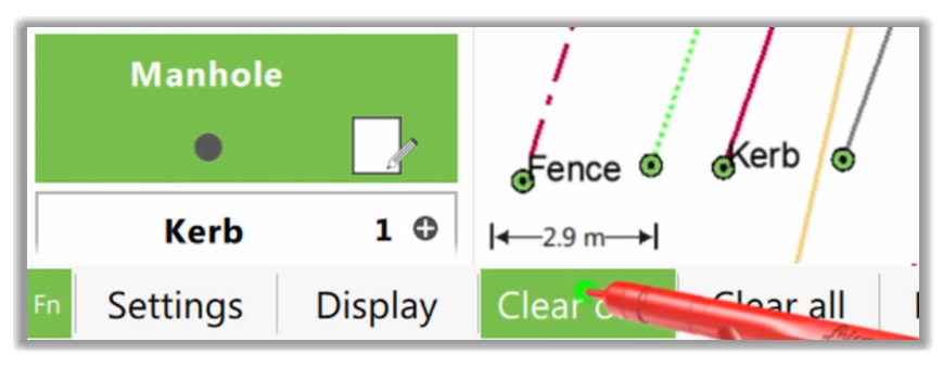
- Now that our list of code boxes is back as we require for measuring the road's cross-sections, we can press Resume and continue with the auto code selection enabled again.
- We could complete the entire job using only these functions, but let's be a little more curious and discover other functions.
Working with geometry within auto code selection
Now, let's take a look at using line geometry within an auto code selection.
- It is easily possible to interact with the code box to modify the lines' geometry as we saw before.
- Doing this with auto code selection enabled is no different than doing it for a single code. We simply select the type of geometry that we would like to use. Here, we are using an arc.
- Then, let's Measure the first point of the arc. But instead of continuing along the arc, we can move on to the next code. We can change its geometry as well. We can change the geometry of any code box whenever we want. We can start and stop features as we please.
- As we continue along this road, using the auto code selection and taking care of the geometry, we quickly and easily collected great data. We can see that we are representing the site in front of us.
Using skip with auto code selection
Now, there are some situations where we're not able to Measure every single code in our list.
- When this happens, we need to use a Skip command.
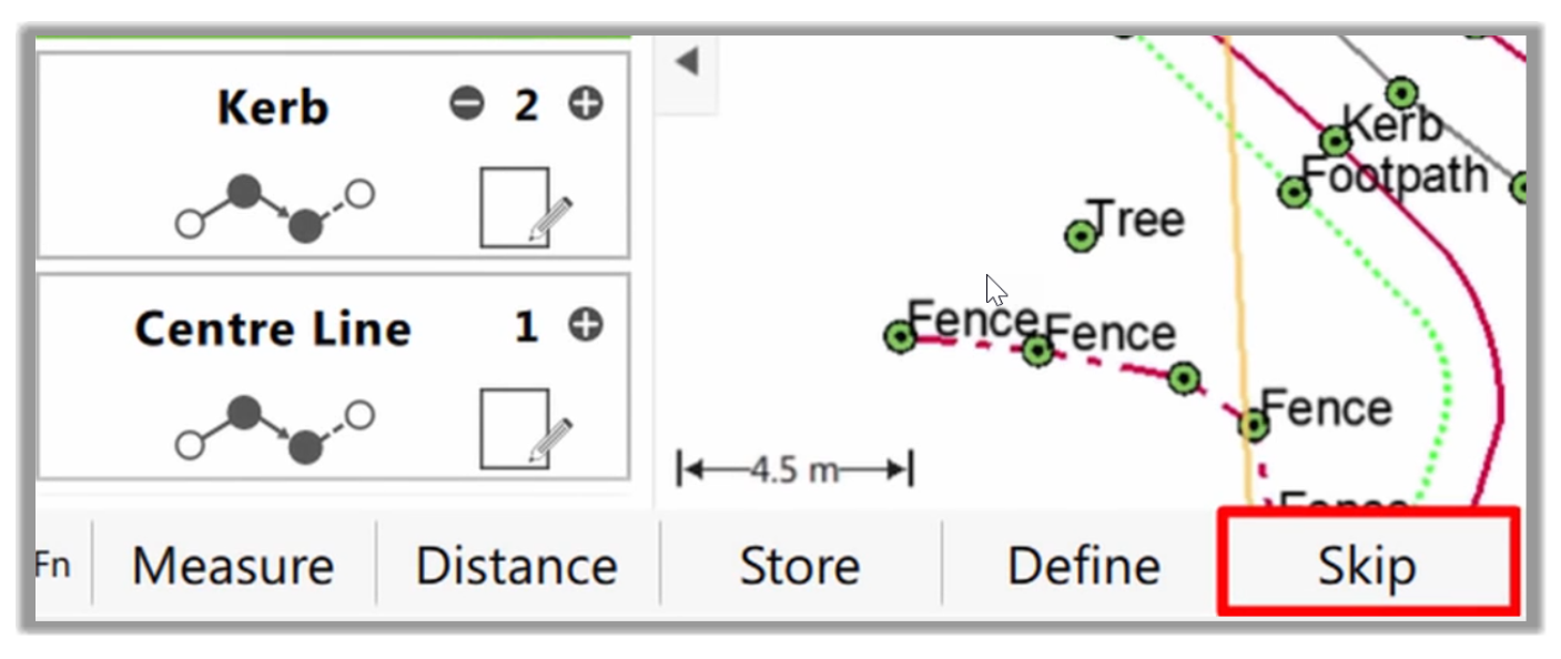
- An example of this could be when we measure across the road where we could see the path, but a parked car stops us from counting the curb where we would like. As we're still being prompted to use that code, we could pause and modify the list of codes to remove Curb from the list. But that is not what we want to do because it is likely that it is just this one time that there is something in the way. Instead, we would use the Skip command, which would be like telling the Controller that we will not make that one specific measurement. But we do want to continue with our auto code selection for the next ones.
2.2.2.6 Manually picking which line to measure
The final feature to now look at is quite different from the Auto code selection because we manually pick which line we want to measure to.
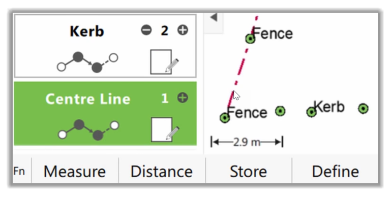
- In this case, instead of using the focus in the code boxes to define what line to measure, we’ll actually tap on the line itself.
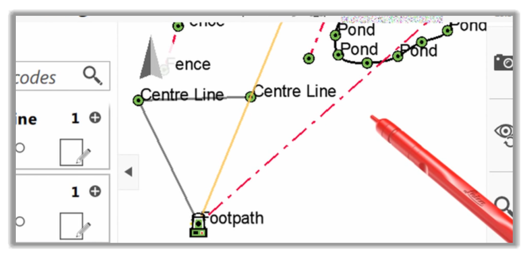
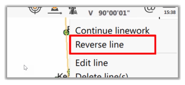
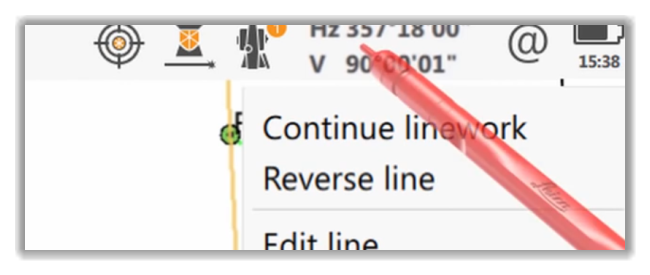
- We will press and hold on that line and then use the menu that appears.
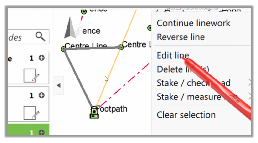
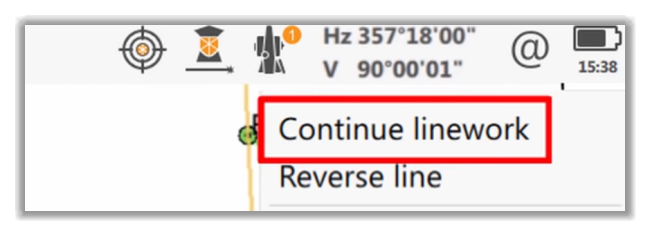
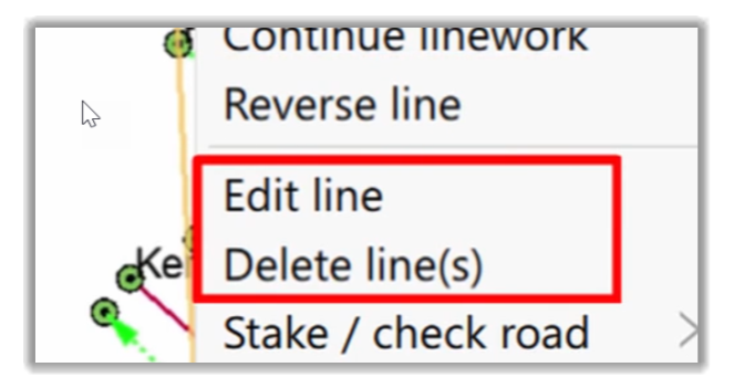
- On this menu, we have quite a few functions regarding this line. We can use Continue linework to allow us to measure more points to it.
- We can Reverse the line so that any new points we measure to it would be used to build up the line in the other direction. In other words, they will be added to the line before its current start point.
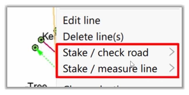
- We can Edit or Delete lines.
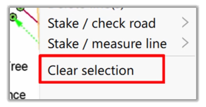
- We can use a line from another app, such as Civil 3D or Inroads.
- Or we can have Leica Captivate deselect the line for us.
- We want to Continue the linework, so we run the command.
- Then, let's make sure that the code box is on the list, and that is the highlighted code box. This means that when we measure, we know that it will be given the correct code and added to the line as we desire.
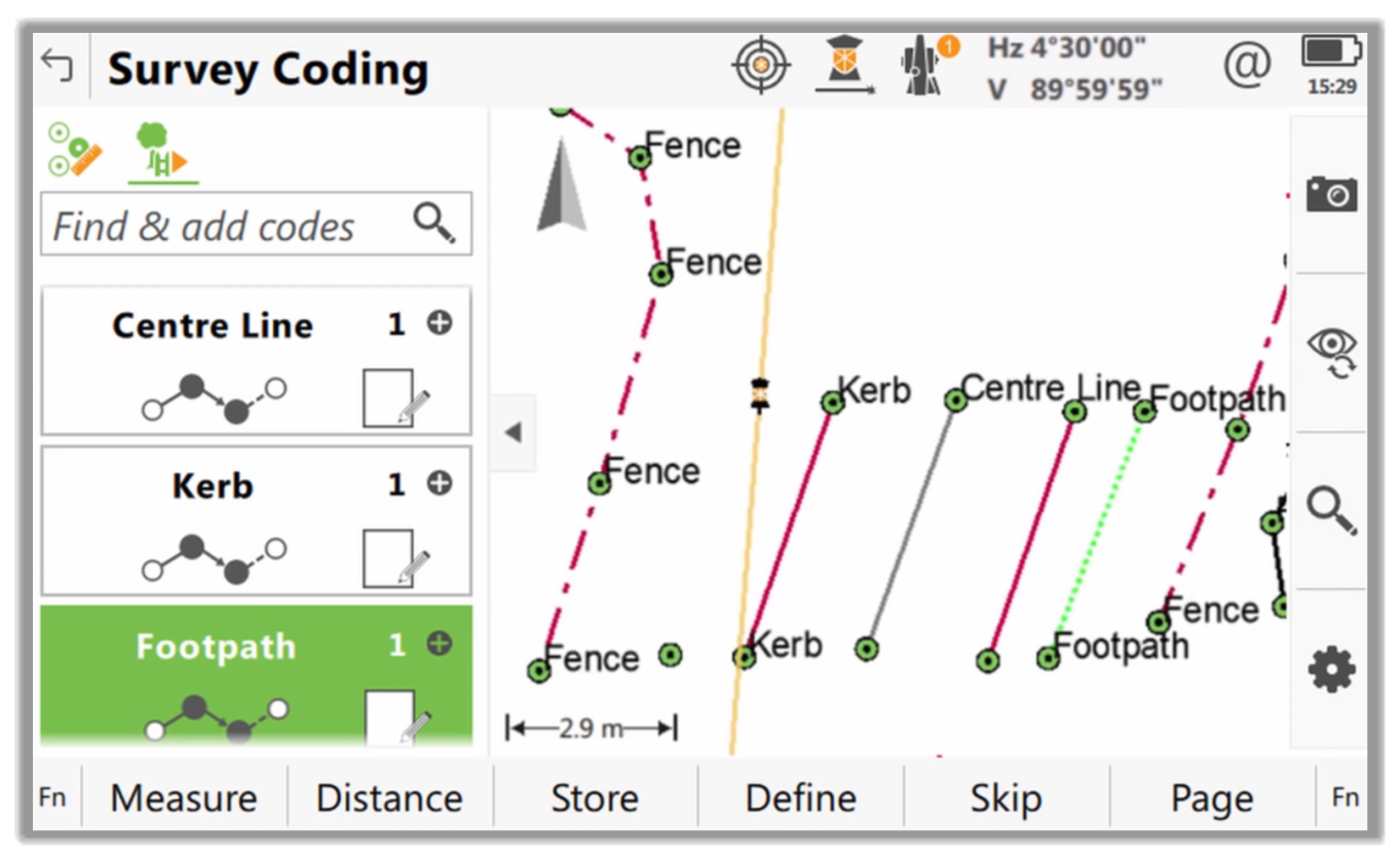
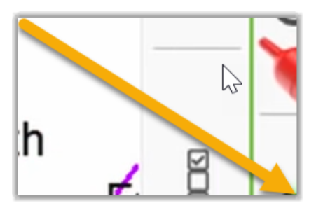
- We could next continue the survey and finish the road far into the distance. However, we're all comfortable doing that now, and instead, we’ll stop and take a look at what we've accomplished so far. The easiest way to do this is to tap the button that hides the split-screen, allowing our data to be shown on the full screen.
- Then we can go into our View configuration.
- Once there, we can turn off the point codes to have an exact visual representation of our site.
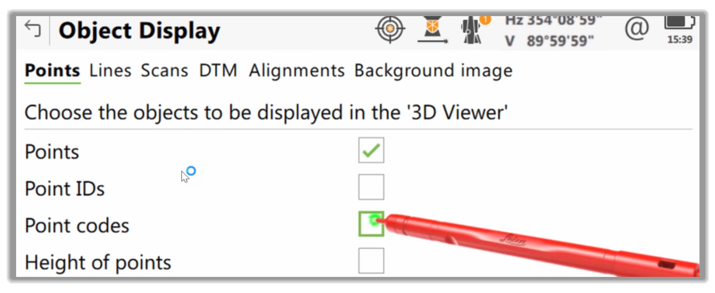
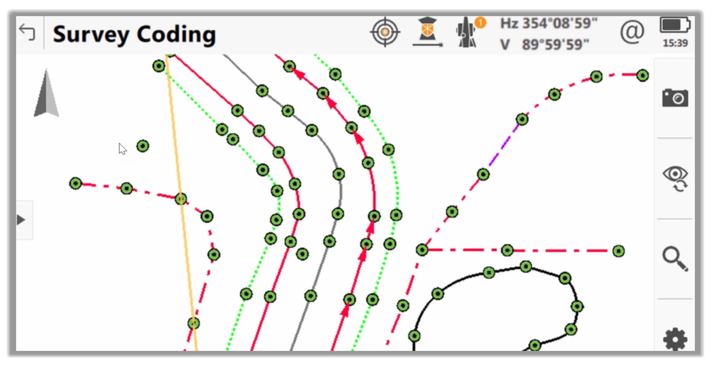
- Here we can see that our data set now fully represents the site we needed to survey, thanks to all of the previously covered features.
-
This is a quick demonstration of how to use Linework Codes in a survey controller. This example shows the case as applied to the Leica Captivate survey controller. This process is pretty standard across the major survey gears on the market. You will notice minor procedural differences, but the concept is pretty universal as it relates to linework code sets.
Full Course and Free Book
-

Civil 3D Essentials Book and Practice Files
Course4.9 average rating (69 reviews)This mini-course offers a downloadable manual of Civil 3D. The eBook covers the features needed to successfully design most civil engineering projects, from field data collection to final design and layout.
Purchase$19.99
-

Advanced Civil 3D: Surveying and Construction
Course5.0 average rating (4 reviews)In this Online Survey and Construction Civil 3D training course, participants will learn and apply the tools offered by Civil 3D, to perform advanced survey and construction tasks.
$99 / year