Civil 3D Survey Traverse
Field to Finish Survey traverse adjustment
Product: Autodesk Civil 3D | Subject: Surveying with Civil 3D
In this exercise, we will learn about Civil 3D Survey traverse analysis and adjustment.
4.3 Traverse Analysis
The first option and probably the most used method for analyzing and correcting survey data is the Traverse Analysis method. We should note that these methods do not correct the errors per se. They will instead distribute them among multiple observations to balance the network. Instead of having one observation totally wrong, the error is distributed among several observations to make the tolerance acceptable for each observation.
The traverse analysis has several options, an example of which is the Compass method.
Let's see how to use it.
In the Compass Rule, the closure error is distributed over the network by adjusting each point's coordinates in a ratio of its distance to the total length.
Let's create a Traverse Analysis.
- Open the practice file Traverse-Compass
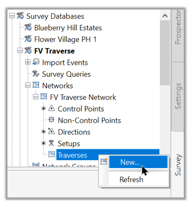
- On the Survey tab, open the FV Traverse collection and scroll down to the Traverses lines.
- Right-click and create a New traverse.
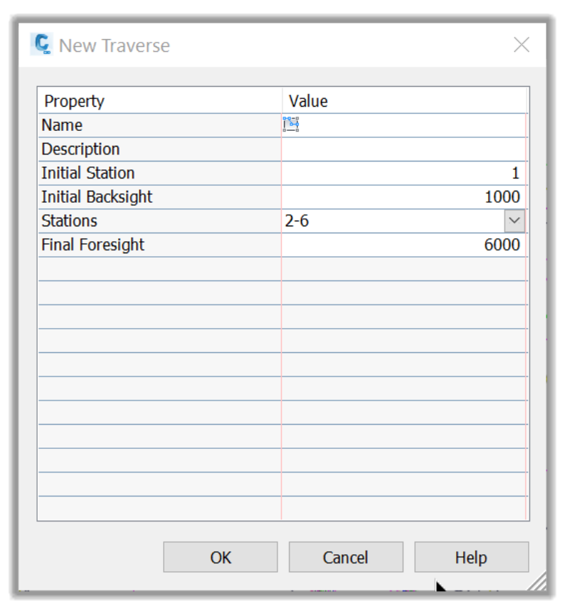
- In the new window, let's enter the following information:
Name: Compass Analysis.
Description: Correction by Compass Analysis
Initial Station: 1
Initial Backsight: 1000
Stations: 2-6
Final Foresight: 6000
- Now that we have specified the analysis parameters, we can click on OK to close the Traverse creation window.
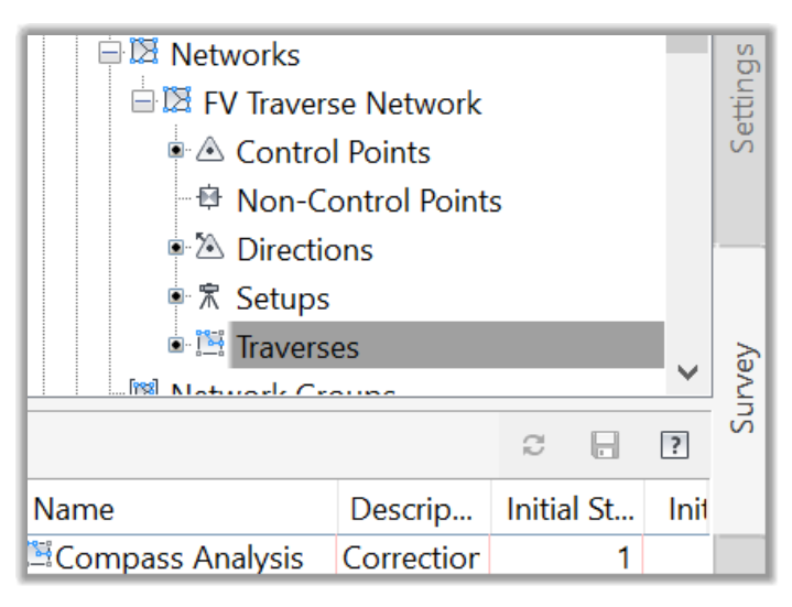
- The new traverse is now created and displayed in the Traverse section of the network.
- We should note that we can always right-click on the traverse and go to its proprieties to adjust the traverse settings.
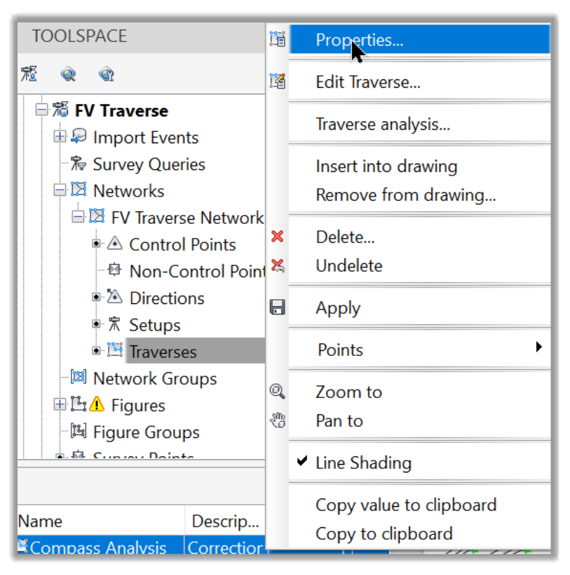
- We can also Edit a traverse, Insert or Remove it from a drawing and Analyze it. Let's run the traverse analysis.
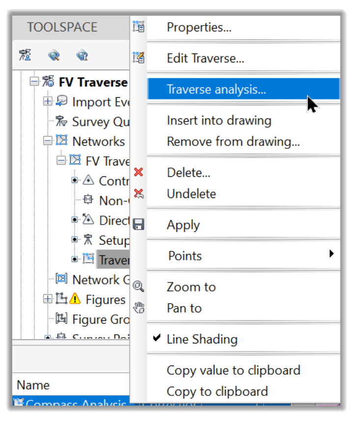
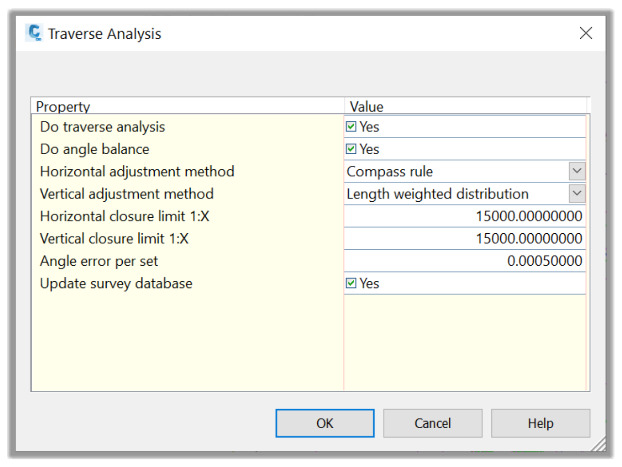
- In the analysis window, let's specify the following settings:
Horizontal Adjustment Method: Compass Rule. As an option, we can choose different other methods, such as the very common Least Squares method.
Let's leave all other parameters to their default and click OK to close the window.
- Once the analysis is executed, several text files are displayed with the following output parameters:
The Raw Closure.trv, which provides the horizontal closure and angular error.
- The Vertical Adjustment.trv showing the raw and adjusted elevations from the vertical adjustment methods.
- The Balanced Angles.trv, where we have the adjusted station coordinates' report derived from balancing the angular error and horizontal closure with no angular error.
- And the .lso file providing the adjusted station coordinates based on the Horizontal Adjustment Type setting (Compass Rule).
- We can save all these files for future reference. Close all the text files for now.
- Now that we have run the traverse analysis, we need to apply the network changes if we are happy with the results. To do that, we need to reprocess the survey data from the Import Events sections. Let's right-click and select Process Linework.
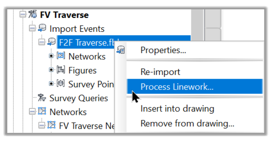
- This will update the network with the new traverse analysis, including Control Points, side shots, figures, etc.
- Due to the similarity with other methods like the Least Squares Analysis, this is more than enough to show how a traverse analysis is done in Civil 3D.
Full Course and Free Book
-

Civil 3D Essentials Book and Practice Files
Course4.9 average rating (69 reviews)This mini-course offers a downloadable manual of Civil 3D. The eBook covers the features needed to successfully design most civil engineering projects, from field data collection to final design and layout.
Purchase$19.99
-

Advanced Civil 3D: Surveying and Construction
Course5.0 average rating (4 reviews)In this Online Survey and Construction Civil 3D training course, participants will learn and apply the tools offered by Civil 3D, to perform advanced survey and construction tasks.
$99 / year