Civil 3D Survey DTM Surface
Field to Finish Surveying
Product: Autodesk Civil 3D | Subject: Surveying with Civil 3D
In this exercise, we will learn about Civil 3D DTM surfaces from text.
DTM (Surface)
A DTM or Digital Terrain Model is simply a Surface in Civil 3D parlance. As we've seen in the Level 2 course, we have different options to create a surface. Let's see a few of these options using Civil 3D exported or exploded entities.
We have recreated various types of entities from our original corridor and road surface in this practice file.
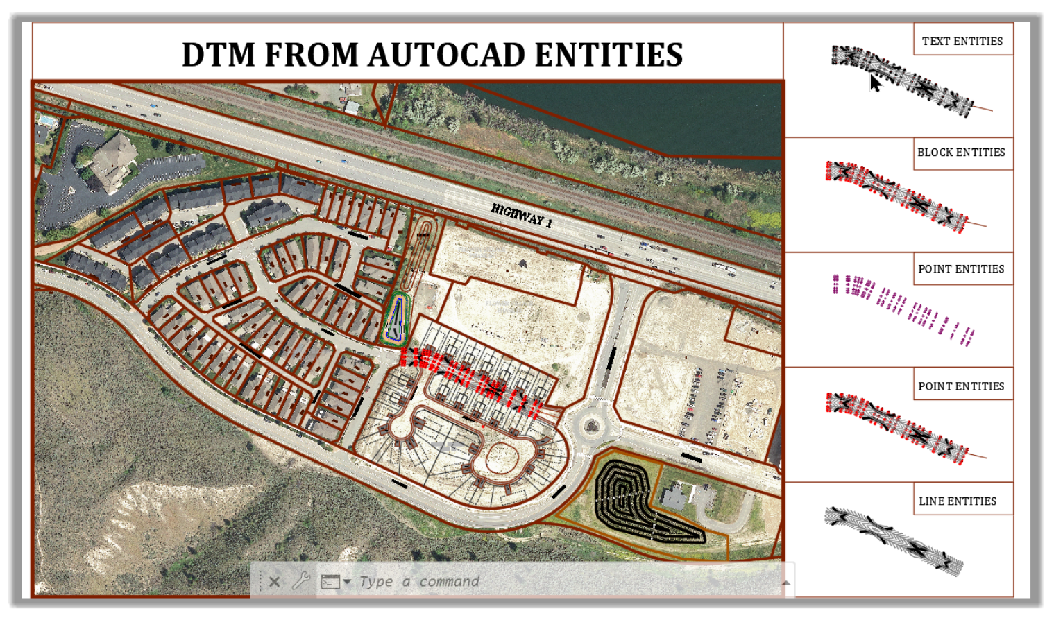
We need to zoom to the appropriate area for each practice exercise, as indicated by the title (Text entities, block entities, point entities, or line entities) and use the objects in that area.
First, let's see start with Text entities.
5.1.1.1 Surface from Text
This scenario is one that is all too common for designers. Surveyors sometimes send them files with survey shots showing only a marker and a text showing an elevation.
When we receive data in this format (as a designer or surveyor), we have some options in Civil 3D to create a DTM from the text entities.
To do this, let’s proceed as follows:
- First, let's open the practice files Reverse-DTM.dwg.
- Then, let's zoom to the Text Entities areas of the drawing.
- In this area, we have exported point entities in text format. We need to recreate the original DTM using the text entities. These text entities represent the elevation of the final surface elevation. First, let's select one of them.
- We notice that the text insertion point (blue grip) is not precisely at the center where the elevation is supposed to be as indicated. Even though the distance is not that big, ideally, we would like the text insertion point to be at the center of the point. So, let's move the text entities to the center of the point. To do this, let's isolate all the entities we want to work with without affecting the other objects in the drawing. Let's select one text and cross next to it.
- Then, let's right-click and Select similar.
- Next, we can isolate the selected objects.
- Now that we have isolated the objects, we need to work with them without affecting other items safely. Now, let's select the text entities only using the Select Similar command.
- Next, we need to make sure we have the Insertion Osnap option activated.
- After that, let's move the text objects from the text insertion point to the center of the point.
- The text insertion point is now precisely at the center of the point marker. When we use the text objects to create a surface, the center of the point will be precisely on the marker.
- Next, we need to ensure that each text entity is precisely at the elevation indicated by the text. To do that, let's Move the Text to the right Elevation. From the Modify tab of the ribbon, let's run the Surface command.
- Then, let's use the Move Text to Elevation command.
- After that, let's select the text objects in the area of interest with a rectangular selection and press Enter.
- Now, each text entity is moved to the elevation indicated in its text. We can verify that by selecting a text entity and check the properties window.
- The text entities are now at the right elevation and can be used to create a surface. Let's create a new surface and call it DTM – Text Entities.
- In the Definition section, let's add some Drawing Entities.
- In the new dialog box, let’s choose Text as the Object Type we would like to add and click OK.
- Then, let's make a rectangular selection and press Enter, to include all text objects in the area of interest.
- The DTM is now created using the elevations of the text entities.
- Let's apply a different style to show the contours better.
- Let's end the isolation.
- We have now created a very close surface to the designed surface, using the design team's text entities. The next step is to export this DTM to the survey gear for field stakeout.
- Next, let's see how to create a DTM using AutoCAD blocks.
5.1.1.2 From AutoCAD Blocks
The next quite common type of data that we encounter are AutoCAD blocks. Let's zoom to the Block Entities area to see how to work with this type of data.
- First, we need to check the block entities to verify if they are at the correct elevations. To do that, let's select one of them and check the elevation from the Properties window.
- Checking a few points, we can see that they are all at the right elevation.
- Sometimes we can also receive block objects with the elevation attached as an attribute. This scenario is mostly encountered when designers are receiving data from surveyors, not the other way around. In that scenario, we can use the Move Blocks to Attribute elevation command to elevate the blocks.
- We don't need this command in the current situation since the blocks are already assigned the right elevations. Therefore, we need to create a surface. Let's call it DTM – Block Entities.
- Next, in the definition section, let's add Drawing Objects.
- In the new dialog box, let's choose to add Blocks and click OK.
- Next, let's select the block using a rectangular selection and press Enter.
- The DTM is now created using the elevations of the block entities.
- Let's apply a different style to show the contours better.
- Next, let's see how to create a DTM using AutoCAD points Entities.
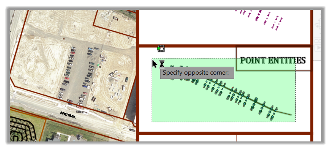
5.1.1.3 Surface AutoCAD Points
The next scenario is when we are provided AutoCAD points. We should note that AutoCAD points are different from Civil 3D Cogo points. They are much less sophisticated as they cannot create point groups, Civil 3D labels, and other advanced design features.
- For this reason, Civil 3D provides us an option to convert AutoCAD points to Civil 3D points using the Convert AutoCAD Points command.
- We only need to do this if we need the Cogo Points to create points groups or use them for other Civil 3D related needs. In the current situation, we don't need Cogo Points to create the DTM. We can directly use the AutoCAD points to create the DTM. Let's create a surface called DTM – Point Entities.
- In the definition section, let's add Drawing objects.
- In the new dialog box, let's select Points in the dropdown menu and click OK.
- Next, let's make a rectangular selection to select all the point objects of interest.
- The DTM is now created using the elevations of the text entities.
- Let's apply a different style to show the contours better.
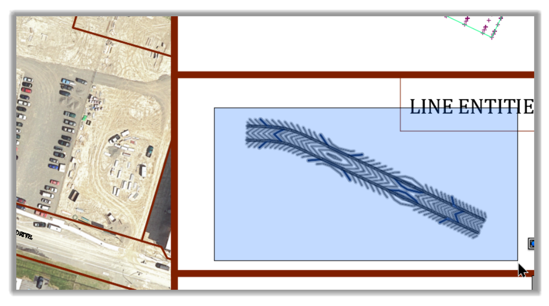
5.1.1.4 Surface from Lines
The next scenario is when we are provided AutoCAD lines. In this scenario, we have several options to use the lines. Among the options, we can use Surface breaklines or contours. We have already covered these options in the Level 2 course. We need to ensure that the entities are AutoCAD lines, not polylines, to use the Line option. If we have polylines, we can always convert them to lines by exploding them.
Let's see how to use the Line Entity option.
- The most important thing is that we need to make sure the lines are assigned the correct elevation.
- Let's create a surface called DTM – Line Entities.
- In the definition section, let's add Drawing objects.
- In the new dialog box, let's select Lines in the dropdown menu and click OK.
- Next, let's make a rectangular selection to select all the line objects of interest.
- The DTM is now created using the elevations of the line entities.
- Let's apply a different style to show the contours better.
Full Course and Free Book
-

Civil 3D Essentials Book and Practice Files
Course4.9 average rating (69 reviews)This mini-course offers a downloadable manual of Civil 3D. The eBook covers the features needed to successfully design most civil engineering projects, from field data collection to final design and layout.
Purchase$19.99
-

Advanced Civil 3D: Surveying and Construction
Course5.0 average rating (4 reviews)In this Online Survey and Construction Civil 3D training course, participants will learn and apply the tools offered by Civil 3D, to perform advanced survey and construction tasks.
$99 / year